Troubleshooting
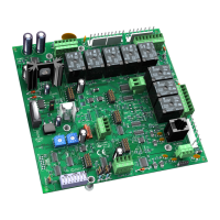
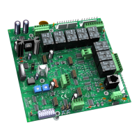
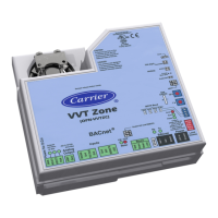
48 VVT Zone Controller
If you have problems mounting, wiring, or addressing the VVT Zone Controller, contact Carrier Control Systems
Support.
LED's
The LED's on the VVT Zone Controller show the status of certain functions.
The VVT Zone Controller has power
The VVT Zone Controller is receiving data from the network segment
The VVT Zone Controller is transmitting data over the network segment
The digital output is active
The actuator motor is turning clockwise
The actuator motor is turning counterclockwise
The Run and Error LED's indicate controller and network status.
1 flash per second
1 flash per second, alternating
with the
The controller files are archiving.
Archive is complete when LED
2 flashes per second
LED stops flashing.
Off Normal
2 flashes per second 2 flashes,
alternating with
Five minute auto-restart delay
after system error LED
2 flashes per second 3 flashes,
then off
The controller has just been
formatted
2 flashes per second On Two or more devices on this
network have the same MS/TP
network address
2 flashes per second 1 flash per second The controller is alone on the
network
 Loading...


