Installation
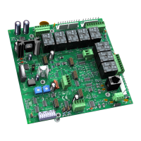
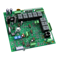
12 VVT Zone Controller
Wiring an SPT sensor
The VVT Zone Controller is connected to a wall-mounted space temperature sensor to monitor room
temperature.
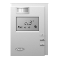
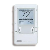
An i-Vu Open Control System offers the following SPT sensors:
SPS
• Local access port
• No operator control
SPPL
Slide potentiometer to adjust setpoint
• MANUAL ON button to override schedule
• LED to show occupied status
• Local access port
SPP
LCD display
• MANUAL ON button to override schedule
• WARMER and COOLER buttons to adjust setpoint
• INFO button to cycle through zone and outside air temperatures,
setpoints, and local override time
• Local access port
You wire SPT sensors to the VVT Zone Controller's Rnet port. An Rnet can consist of any of the following
combinations of devices wired in a daisy-chain configuration:
• 1 SPT Plus or SPT Pro
• 1–4 SPT Standards
• 1–4 SPT Standards, and 1 SPT Plus or SPT Pro
• Any of the above combinations, plus up to 2 BACview
6
NOTES
's but no more than 6 devices total
• If you have 2 BACview
6
's, the second BACview
6
must have a separate power supply with the same
ground as the controller.
• If the Rnet has multiple SPT Standard sensors, you must give each a unique address on the Rnet. See
the Carrier Sensors Installation Guide.
• If the Rnet has multiple BACviews, you must give each a unique address on the Rnet. See the BACview
Installation and User Guide.
Rnet wiring specifications
NOTE Use the specified type of wire and cable for maximum signal integrity.
Description 4 conductor, unshielded, CMP, plenum rated cable
Conductor 18 AWG
Maximum length 500 feet (152 meters)
Recommended coloring Jacket: White
Wiring: Black, white, green, red
UL temperature rating 32–167°F (0–75°C)
 Loading...


