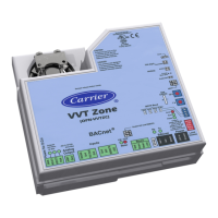
VVT Zone Controller 13
Voltage 300 Vac, power limited
Listing UL: NEC CL2P, or better
To wire the SPT sensor to the controller
1 Partially cut, then bend and pull off the outer jacket of the Rnet cable(s). Do not nick the inner insulation.
Strip about .25 inch (.6 cm) of the inner insulation from each wire.
Outer Jacket
Inner insulation
.25 in.
(.6 cm)
2 Wire each terminal on the sensor to the same terminal on the controller. See diagram below.
NOTE Carrier recommends that you use the following Rnet wiring scheme:
Red
Black
White
Green
+12V
Rnet-
Rnet+
Gnd
3 Verify that the Rnet jumper is set to Rnet.
 Loading...


