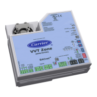
Installation
6 VVT Zone Controller
To install the VVT Zone Controller:
1 Mount the controller to the VVT box. (page 7)
2 Wire the controller for power. (page 8)
3 Set the controller's address. (page 9)
4 Wire the controller to the MS/TP network. (page 10)
5 Wire sensor(s) to the controller. (page 11)
6 Wire equipment to the controller's outputs. (page 21)
Field-supplied hardware
Each zone controller installation requires the following field-supplied components:
• zone terminal unit
• round or rectangular mounting bracket
• space temperature sensor
• supply air temperature sensor
• 4x2-in. electrical box
• transformer— 24 Vac, 40 VA
• two no. 10 x 1/2-in. sheet metal screws (to secure SAT sensor to duct)
• two no. 6-32 x 5/8-in. screws (to mount space temperature sensor base to electrical box)
• wiring
• bushings (required when mounting SAT sensor in a duct 6-in. or less in diameter)
Optional:
• contactors (if required for fan or electric heat)
• indoor air quality sensor
• relative humidity sensor
• 2 screws and 2 hollow wall anchors (to mount relative humidity sensor directly to wall)
• valve and actuator for hot water heat (if required)
 Loading...


