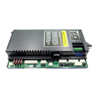
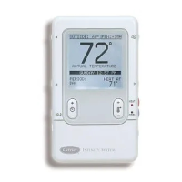
Appendix A: VVT Zone Controller Points/Properties
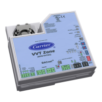
60 VVT Zone Controller
Service Configuration
i-Vu / Field Assistant:
BACview:
>
>
>
Service Configuration
HOME
>
>
– The type of zone terminal that the controller is installed on. D:
R:
Single Duct
Single Duct
Parallel
Series Fan
– Used by the VVT Master to calculate the weighted average demand. If
the zone damper is round, enter its diameter. If rectangular, enter 0.
D:
R:
6.00 in.
0 to 100.00 in
– Used by the VVT Master to calculate the weighted average
demand. If the damper is rectangular, enter its area (width x height). If the damper is
round, enter 0.
D:
R:
0 sq.in.
0 to 9999 sq.in.
– Enable if the controller's analog output is used for an external
high-torque or slave actuator. Enabling this setting disables the output for Modulating Hot
Water or Combination reheat functions.
D:
R:
Disable
Disable/Enable
– The type of supplemental reheat that the zone controller will control. The heat
may be used with system heat, depending on the space temperature demand.
Options:
– no heat
– ducted or baseboard modulating hot water
– two position hot water
– ducted or baseboard electric heat
– combination baseboard modulating hot water and ducted staged electric
heat
D:
R:
None
None
Modulating
Two Position
Staged EH
Combination
– Determines whether the zone is using ducted heat or baseboard. If
is
, set this field to
for ducted heat.
D:
R:
Yes
No/Yes
– The number heat stages when the
is
. Fan
powered terminals are limited to no more than 2 stages.
D:
R:
Two stages
One stage
Two stages
Three stages
– Two Position hot water only - The hot water valve's position with no power
applied to the valve.
D:
R:
NC
NC/NO (normally
closed/normally open)
– The type of sensor used on the controller's
input. This
setting determines the optional control functionality.
Options:
Relative humidity for zone dehumidification
– Indoor air quality to DCV control
D:
R:
None
None
RH Sensor
IAQ Sensor
D: – Zone dehumidification control.
R:
Disable
Disable/Enable
– Demand control ventilation control. D:
R:
Disable
Disable/Enable
 Loading...


