The TruVu™ VAVB3-E2 is an advanced application controller designed for controlling zone temperature in Variable Air Volume (VAV) applications, specifically with single duct or fan-powered terminals. It regulates the flow of conditioned air into a space and supports buildings with diverse loading conditions by controlling local terminal supplemental heat. The controller can be used in VAV applications and can also be included in a VVT system.
Function Description:
The TV-VAVB3-E2 runs two control programs: a VAV Product Integrated Control (PIC) program and an optional programmable Zone Controller II program (or up to two Zone Controller II programs). It supports BACnet/IP communications on its 10/100 Ethernet port, functioning as a single node in a daisy-chain configuration or as part of a network using a ring topology. DHCP IP addressing is supported. The controller features built-in network diagnostic capture functionality for troubleshooting and network statistics that can be viewed numerically or as trend graphs. It includes built-in airflow sensors and supports Rnet and Act Net devices. The TV-VAVB3-E2 is compatible with the i-Vu® v7.0 or later system with the latest cumulative patch. It provides four universal inputs, three binary outputs, and two analog outputs.
The controller manages zone temperature by modulating its damper actuator to control primary airflow. It uses PID control to calculate the airflow setpoint based on the air source mode and the difference between the zone’s temperature and setpoints. The air source mode determines if the primary air can meet the zone’s needs. If the zone controller is in a linked system, the air source determines the mode. If stand-alone or if linkage communication fails, the controller’s SAT sensor determines the mode. The damper is positioned to modulate airflow setpoint between configurable minimum and maximum airflow based on occupancy status, ensuring sufficient minimum airflow and ventilation during occupied periods.
Heating Capabilities:
The TV-VAVB3-E2 can be configured for various heat types:
- Modulating Hot Water/Steam: Modulates a normally closed or open hot water or steam valve connected to the discharge air heating coil to satisfy heating requirements. For ducted heat, it supplements primary air heat, controlling SAT not to exceed Maximum Heating SAT. For baseboard heating, it modulates the valve to maintain zone temperature at the heating setpoint.
- Two Position Hot Water/Steam: Operates a normally closed or open hot water or steam valve, opening and closing as needed. Similar SAT control for ducted heat and zone temperature control for baseboard heat.
- Staged Electric Heat: Operates 1, 2, or 3 stages of electric heat (up to 2 stages with Series/Parallel Fan, up to 3 stages for Single duct). For ducted heat, it supplements primary air heat, controlling SAT not to exceed Maximum Heating SAT. For baseboard heat, stages are controlled to maintain zone temperature.
- Combination Modulating Baseboard/Staged Electric Heat: Modulates a hot water or steam valve for perimeter baseboard radiation and controls up to 2 stages of ducted electric heat.
- SCR Electric Heat: Modulates an SCR heat output connected to the SCR electric heat control input.
- CV Modulating Heat: Modulates a normally closed or open hot water or steam valve connected to a perimeter baseboard radiation system or discharge air heating coil.
Demand Control Ventilation (DCV) and Dehumidification:
The IN-01 input supports an optional CO2 or Relative Humidity (RH) sensor, with a 5-volt maximum output (configurable 0–5 or 1–5 volts). The controller can also use ZS Sensors with CO2 and/or RH connected to the Rnet. If multiple sensors are present, DCV and dehumidification are based on the highest sensor value. The controller can override temperature control to respond to increasing CO2 levels when occupied, increasing airflow from Occupied Min Airflow to DCV Max Vent Airflow. For dehumidification, it monitors the RH sensor and can provide dehumidification if the value exceeds the Occupied RH Control Setpoint when occupied and not heating, and the air source is in cooling mode.
Occupancy:
Operation depends on occupancy schedules (local or system-wide) or remote occupancy override (via IN-04 input). The Learning Adaptive Optimal Start function adjusts unoccupied setpoints to achieve occupied setpoints by the scheduled time.
Alarms:
The TV-VAVB3-E2 monitors various conditions and generates alarms:
- Space Temp Sensor Alarm: Generated if no valid space temperature value is available, disabling local heating/cooling.
- Space Temperature Alarm: Generated if space temperature exceeds alarm setpoints for more than 15 minutes.
- Supply Air Temperature Alarm: Generated if SAT exceeds High SAT Alarm Limit or falls below Low SAT Alarm Limit for more than 5 minutes.
- Space Relative Humidity Alarm: Generated if RH sensor value exceeds Occupied RH Control Setpoint (occupied) or Unocc High RH Alarm Limit (unoccupied).
- Indoor Air Quality Alarm: Generated during occupied periods if CO2 sensor value exceeds Occupied High CO2 Alarm Limit.
- Filter Alarm: For fan-powered terminals, generated if accumulated fan operation hours exceed Filter Service Alarm Timer limit.
- Airside Linkage Alarm: Generated if a slave controller loses linkage information for 5 minutes or if a VVT Master loses communication with its air source.
- Smart HWV 1 Alarm: Triggered if the difference between Hot Water Valve output command and feedback input exceeds a value for 1 minute.
- Heating Valve Cycling Alarm: Occurs if the input cycles more than a specified number of times in a given period.
- Heating Valve Failure Alarm: Occurs if discharge air temperature does not rise a specified amount within a given time after the heating coil valve command is above a certain percentage.
Important Technical Specifications:
- Driver: drv_fwex_.driverx
- Control Programs: 2 (1 VAV PIC + 1 Zone Controller II, or 2 Zone Controller II)
- BACnet Objects: Max 12000
- Third-party BACnet Integration Points: 100 (BACnet/IP network only)
- Power: 24 Vac ±15%, 50–60 Hz, 50 VA; 24 Vdc ±10%, 18 W
- Actuator: Belimo brushless DC motor, 45 inch-pounds (5 Nm) torque, 154 seconds runtime
- Ethernet Ports (Eth0, Eth1): 10/100 BaseT, full duplex, for BACnet/IP and/or BACnet/Ethernet communication. Traffic not destined for the controller is repeated to the other port.
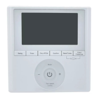
- Rnet Port: Supports up to 10 wireless and/or ZS sensors, Equipment Touch, TruVu™ ET Display, and Wireless Adapter. Supplies 12 Vdc/260 mA power. Communicates at 115.2 kbps.
- Comm/Service USB Ports: USB 2.0 host ports for local setup, troubleshooting, TruVu™ ET Display, or Carrier wireless service adapter.
- Act Net Port: Supports up to 5 Act Net addresses (Address 1 reserved for built-in actuator, 2 & 3 for VAV Zone II Secondary Duct, 4 & 5 for others). Max power for Act Net devices: 25 VA (1 A) AC supply, 15W (0.625A) DC supply. Bus length up to 300 feet (91.44 meters) with 18 AWG or larger copper conductors.
- Universal Inputs: 4 (configurable for 0–5 Vdc, 0–10 Vdc, thermistor, dry contact, or pulse counter). Input resolution: 12 bit A/D. Input pulse frequency: 10 pulses/second (min pulse width 50 msec).
- Analog Outputs: 2 (0–10 Vdc), configurable as 12 Vdc pulse width modulated (PWM) control signal (80 Hz). Output resolution: 12 bit D/A.
- Binary Outputs: 1 bank of 3 N.O. relays. Each relay contact rated at 3.75 A max. @ 30 Vac/Vdc. Bank limited to Class 2 requirements of 100 VA / 4.2 A. Configured normally open.
- Integral Static Pressure Sensor: Precision differential pressure sensor 0–2 in. H2O, sensitive to ±0.001 in. H2O. Accuracy ±3% at 2 in. H2O.
- Memory: 4 GBs eMMC Flash, 256 MB DDR3 DRAM. User data archived every 90 seconds and on firmware restart.
- Real-time Clock: Keeps time for up to 3 days without power.
- Protection: Field-replaceable glass fuse (3A fast-acting 5mm x 20mm).
- LED Status Indicators: Tricolor Net LED (network status), Tricolor Sys LED (controller status), Tx/Rx LEDs for Port S1 and Ethernet ports, Output LEDs (output status), Prog 1/2 LEDs (customizable), Locator LED (commissioning/damper rotation).
- Environmental Operating Range: 32–122°F (0–50°C), 10–95% relative humidity, non-condensing.
- Physical: Fire-retardant plastic ABS, UL94-5VA. Screw-type terminal blocks (0.2 in / 5.08 mm pitch).
- Dimensions (A x B x C x D x Depth): 8.39 in. (21.30 cm) x 5.95 in. (15.11 cm) x 6.00 in. (15.24 cm) x 7.52 in. (19.10 cm) x 3.83 in. (9.72 cm).
- Weight: 1.8 lbs (0.82 kg).
- MTBF @ 77°F (25°C): 184,811 hours.
- BACnet Support: Conforms to B-AAC and B-BMD, Protocol Revision 15.
Usage Features:
- Mounting: Mounts to VAV terminal by sliding clamp assembly onto damper shaft. Damper shaft must be fully closed first. An enclosure is recommended, with at least 1 foot (.3 m) clearance for service access.
- Addressing: Can be addressed via Comm/Service USB ports using a wireless service adapter or USB cable. Supports DHCP or custom static IP addressing. The Local Network tab allows discovery and configuration of multiple controllers on a single network.
- Sensor Wiring: Supports T55, Supply Air Temperature, CO2, Relative Humidity, and remote occupancy sensors. Input wiring specifications vary by signal type (thermistor/dry contact: 22 AWG, shielded; 0-5/0-10 Vdc: 26 AWG, shielded; pulse counter: 22 AWG, shielded). Max length 1000 feet (305 meters) for inputs.
- Output Wiring: Analog outputs for 0-10 Vdc devices (min 500 Ohms resistance to ground). Binary outputs for relays (up to 3.75 A, 30 Vac/Vdc).
- Airflow Sensor: Built-in for single duct or fan-powered applications. For dual duct, uses VAV Zone II Secondary Duct connected to Act Net port. Tubing for airflow sensor should be at least 2 ft (.61 meters) long, not exceeding 16.4 ft (5 meters) combined length.
- Airflow Control Microblock Setup: Configured in Snap application for Cooling (single duct) or Cooling/Heating (dual duct).
- System Balancing: Uses i-Vu®/Field Assistant applications or Test & Balance tool to calibrate damper travel and airflow. Includes steps for setting damper size, calibrating zero airflow, and adjusting cooling/heating airflow.
- Network Statistic Trends: Allows setting up trends for network statistics, including error rates and packet rates.
Maintenance Features:
- Troubleshooting LEDs: Different LED patterns (Red, Blue, Green, Magenta) indicate various conditions (Ethernet connection problems, firmware errors, communication errors, system status, operating system changes) and suggest possible solutions like cycling power, changing protocol, or downloading driver.
- Module Status Report: Provides information on controller and network communication status, accessible via i-Vu®, Field Assistant, or ModStat tab.
- Device Log: Gathers diagnostic information for troubleshooting, downloadable as a Wireshark-compatible .tgz file.
- Serial Number Retrieval: Serial number can be found on a Module Status report, a sticker on the cover, or laser-etched on the circuit board.
- Out of Service: Option to prevent i-Vu® from communicating with the controller for troubleshooting.
- Fuse Replacement: Instructions for replacing the 3 A, fast-acting, 5mm x 20mm glass fuse.
- Revert to Default Settings: Erases all archived information and user-configuration settings, requiring manual reconfiguration of communications and firewall information.