Start-up
TruVu™ VAVB3-E2 CARRIER CORPORATION ©2022
Installation and Start-up Guide All rights reserved
57
Commissioning the TV-VAVB3-E2
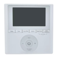
Using Field Assistant or the i-Vu® application:
1 Set damper size. Go to Properties > Configuration > Service Configuration > Flow Control > Details tab >
Manufacturer's specified air flow at 1" water column and enter the correct cfm for the damper size.
2 Calibrate the damper travel.
a) Go to Properties > Configuration > Service Configuration > Flow Control > Details tab > Test and
Balance. Click Close Damper and verify it goes to the closed position.
b) Click Dampers Full Open and verify it goes to the full open position.
c) Verify that the air source is off, and then calibrate the zero airflow reading at the terminal control. Click
Zero Flow and verify the damper goes to the fully closed position and the airflow transducer is calibrated.
Once the Autozero complete message is displayed, make sure the Measured Flow column under
Calibration parameters for Zero Flow reads near zero cfm (liters/second) and the sensor reading should
be less than 0.03.
d) Click Automatic Control to return the damper to normal operation.
3 For Parallel or Series Fan terminals – In the Locks section, select the Fan's Lock value to checkbox, then
select On in the drop-down list. Click Apply. Verify the fan's operation.
4 For modulating hot water reheat – Go to Properties > I/O Points tab, then lock Hot Water Valve to 100%. If
the controller is configured for Single Duct, make sure the air source fan is on. If ducted heat, verify the heat
works by verifying that the SAT rises. For baseboard heat, physically check the heating element for proper
temperature rise. Release the Hot Water Valve.
5 Release the fan.
6 If the controller is part of a linked system, verify Linkage > Airside Linkage Status shows Active.
Balancing the system using the i-Vu®/Field Assistant applications
Most VAV system airflow designs are based on cooling requirements which require a greater cfm (liters/second)
flow than heating requirements. Using this balancing procedure, you adjust the cooling airflow first. If the heating
and cooling maximum airflow requirements are the same, you do not need to balance the heating airflow.
NOTE We recommend that the total heating minimum airflow settings for all the zones in the system be set to
maintain the air source’s design minimum heat cfm (liters/second) airflow across its heat exchanger to prevent
damage to the equipment.
The following procedures instruct you to use the i-Vu® application or Field Assistant to balance the system.
However, you can also use the Test & Balance tool that includes global commands to assist you in balancing the
system.