Wiring sensors to the TV-VAVB3-E2's inputs
TruVu™ VAVB3-E2 CARRIER CORPORATION ©2022
Installation and Start-up Guide All rights reserved
36
To wire the CO2 sensor to the controller
Part #33ZCSPTCO2LCD-01 (Display model)
Part #33ZCSPTCO2-01 (No display)
Part #33ZCT55CO2 (No display)
A CO
2
sensor monitors carbon dioxide levels. As CO
2
levels increase in a linked system, IAQ is provided to the air
source. These sensors also monitor temperature using a 10K thermistor.
A CO
2
sensor can be wall-mounted or mounted in a return air duct. (Duct installation requires an Aspirator Box
Accessory - Part #33ZCASPCO2.)
The sensor has a range of 0–2000 ppm and a linear 4-20 mA output. This is converted to 1-5 Vdc by a 250 Ohm,
1/4 watt, 2% tolerance resistor connected across the zone controller's CO
2
input terminals.
NOTE Do not use a relative humidity sensor and CO
2
sensor on the same zone controller.
#33ZCSPTCO2
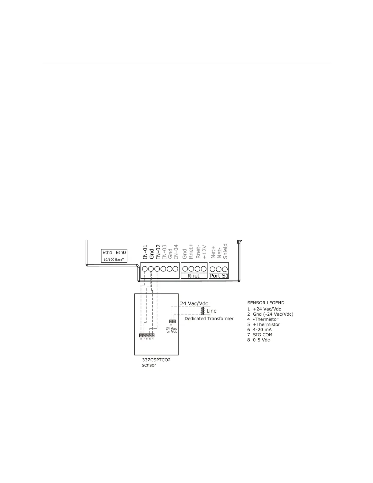
1 Wire the sensor to the controller. See appropriate diagram below.
2 Verify the J7 jumper on the sensor is set to 0-5 Vdc.
Wiring diagram for #33ZCSPTCO2:
#33ZCT55CO2
1 Wire the sensor to the controller. See appropriate diagram below.
2 Install a field supplied 250 Ohm 1/4 watt 2% tolerance resistor across the controller's IN-01 and Gnd
terminals.