Start-up
TruVu™ VAVB3-E2 CARRIER CORPORATION ©2022
Installation and Start-up Guide All rights reserved
55
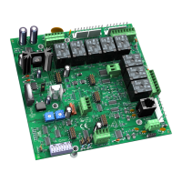
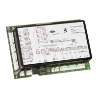
Use one of the following interfaces to start up, access information, read sensor values, and test the controller.
1
Requires a USB Link (Part #USB-L).
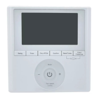
2
See the Equipment Touch Installation and Setup Guide for detailed instructions.
3
See the TruVu™ ET Display (part# EQT2) Installation and Setup Guide for detailed instructions.
4
See the System Touch Installation and Setup Guide for detailed instructions.
CAUTION If multiple controllers share power but polarity was not maintained when they were wired, the
difference between the controller's ground and the computer's AC power ground could damage the USB Link and
the controller. If you are not sure of the wiring polarity, use a USB isolator between the computer and the USB
Link. Purchase a USB isolator online from a third-party manufacturer.
Configuring the TV-VAVB3-E2's properties
To start up the TV-VAVB3-E2, you must configure certain points and properties. Appendix A (page 107) is a
complete list of all the points and properties, with descriptions, defaults, and ranges. These properties affect the
unit operation and/or control. Review and understand the meaning and purpose of each property before changing
it.
• Unit Configuration properties
• Setpoint Configuration properties
• Service Configuration properties
• Linkage properties (page 133)
See Appendix A (page 107) for a complete list of the controller's points/properties.
NOTE Engineering units shown in this document in the defaults and ranges are strictly for reference. You must
enter an integer only.