— 39 —
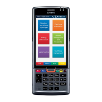
13. Separate the shield plate from LCD module carefully by using
case opener. Spare parts of LCD module dose not include the
shield plate, and shild paper and insullation seal on LCD cable.
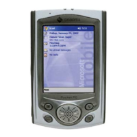
14. The repair is available as set of Main PCB + Inverter PCB + RAM PCB. The details will be informed by
Service Bulletine separately.
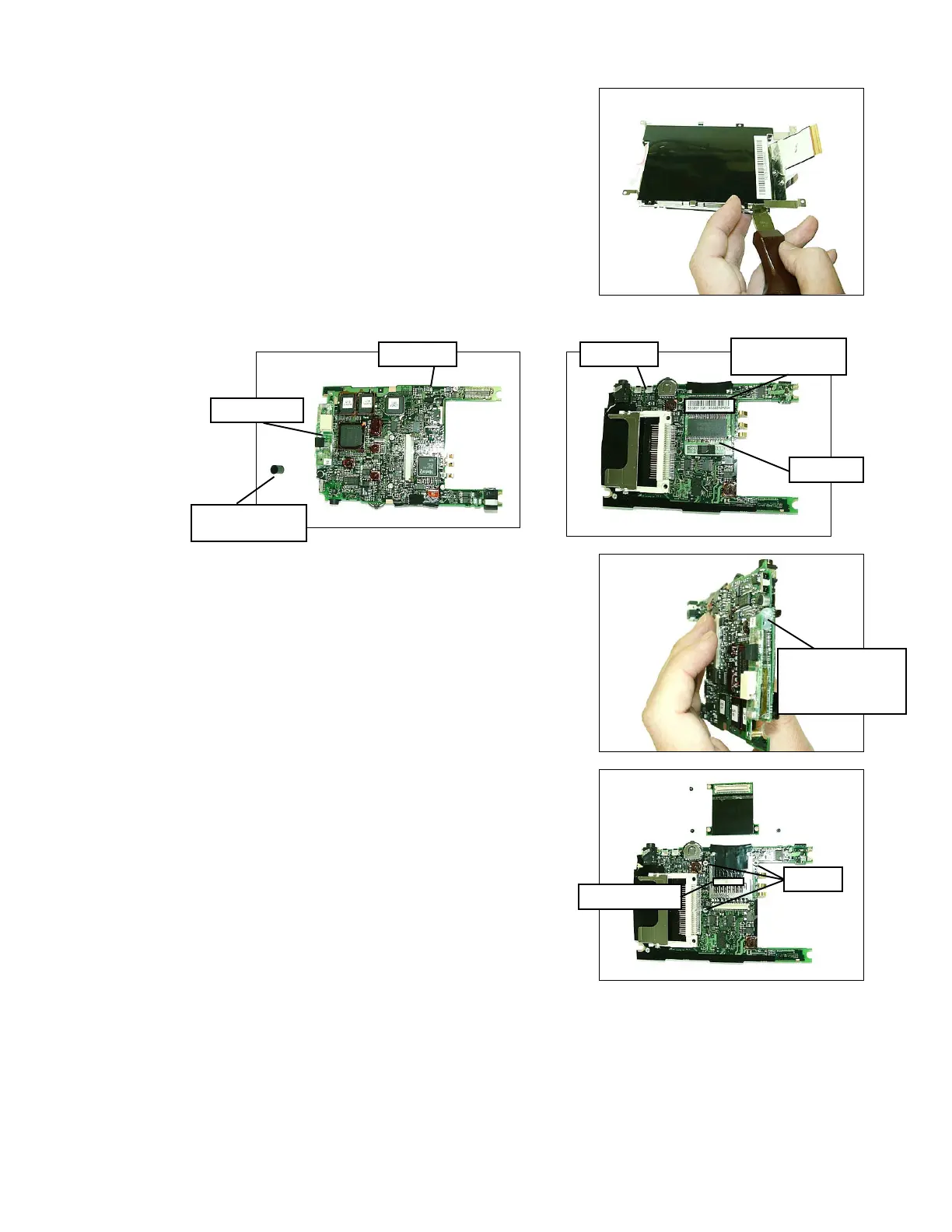
15. The inverter PCB is fixed by connector and hot melt glue which
can be remover by heat blower. However do not touch as long
as inverter fault.
16. RAM PCB is fixed by screws and double side adhesive tape.
However do not touch as long as RAM PCB fault.
Inverter PCB
Remove from
Main PCB
Serial No. seal of
Main PCB
RAM PCB
Hot melt gule to fix
connector, can be
remove by heat
blower
Screws
Screws
Adhesive tape
Main PCB Main PCB