88
Legenda schema elettrico
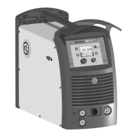
DIGITECH 400 PULSED
Key to the electrical diagram
DIGITECH 400 PULSED
1) Bobina contattore di linea
2) Condensatori
3) Connettore alimentazione 400V
4) Connettore cavo interconnessione
5) Connettore alimentazione HR26
6) Contattore di linea
7) Condensatore di protezione poli d'uscita postivo e
negativo
8) Connettore sensore effetto hall
9) Diodi snubber
10) Diodi secondari
11) Fusibile primario trasformatore ausiliario
12) Fusibile secondario trasformatore ausiliario
13) Filtro EMC
14) Inizio bobina
15) Modulo IGBT
16) Interruttore di linea
17) Induttore
18) Motore ventilatore
19) Resistori carica condensatori
20) Resistori di scarica
21) Resistore di snubber
22) Resistore secondario
23) Resistore sensore di tensione
24) Tastiera a membrana
25) Raddrizzatore primario
26) Scaricatore di tensione
27) Scheda digitale CPU pannello frontale
28) Scheda digitale pannello frontale
29) Scheda controllo inverter
30) Connettore seriale modem esterno
31) Scheda relè HR26 ventilatori e contattore
32) Trasformatore ausiliario
33) Trasformatore di corrente ramo IGBT
34) Trasformatore di corrente ramo primario
35) Sonda di corrente ad effetto Hall
36) Toroidi soppressione disturbi
37) Termostato circuito primario
38) Termostato circuito secondario
39) Trasformatore di potenza principale
40) Varistore snubber diodi d’uscita
1) Line contact coil
2) Condensers
3) 400V input voltage connector
4) Interconnection cable connector
5) HR26 input voltage connector
6) Line contact
7) Exit protection capacitor (positive/negative)
8) Hall effect sensor connector
9) Snubber diodes
10) Secundary diodes
11) Auxiliary transformer primary fuse
12) Auxiliary transformer secundary fuse
13) EMC filter
14) Coil start
15) IGBT unit
16) Supply switch
17) Inductor
18) Fan motor
19) Condensers load resistors
20) Discharge resistors
21) Snubber resistor
22) Secundary resistor
23) Voltage sensor resistor
24) Membrane keyboard
25) Primary rectifier
26) Voltage surge suppressor
27) Front panel CPU PCB
28) Front panel digital circuit board
29) Inverter control PCB
30) External modem serial connector
31) Fans and contactor HR26 relay circuit board
32) Auxiliary transformer
33) IGBT power transformer
34) Mains power transformer
35) Hall current probe
36) Disturbances suppression toroid
37) Primary circuit thermostat
38) Secundari circuit thermostat
39) Main power transformer
40) Output diodes snubber varistor
Legenda colori Colour key
Ar Arancio
AR Azzurro Rosso
Az Azzurro
Bc Bianco
Bl Blu
BN Bianco Nero
BR Bianco Rosso
Gl Giallo
GV Giallo Verde
Gg Grigio
Mr Marrone
NA Nero Azzurro
Nr Nero
Ro Rosa
Rs Rosso
Vd Verde
Vl Viola
Ar Orange
AR Sky Blue Red
Az Sky Blue
Bc White
Bl Blue
BN White Black
BR White Red
Gl Yellow
GV Yellow Green
Gg Grey
Mr Brown
NA Black Sky Blue
Nr Black
Ro Pink
Rs Red
Vd Green
Vl Violet
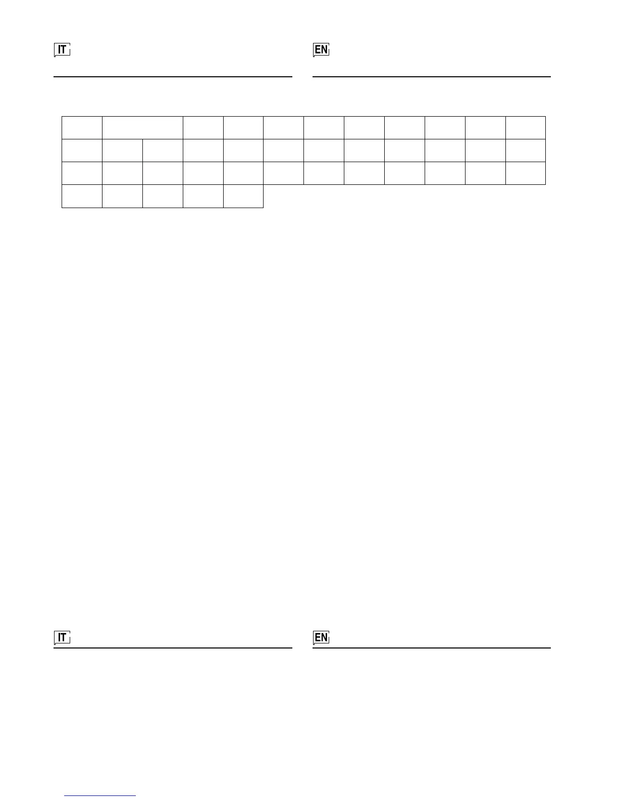
BCL C1-2-3-4-5 CA CCI CHR CL Cp CSH D1 D2 F1
F2 F-EMC Ib IB1-2 IL L MV1-2 R1 R2 R3 R4 R5
RK RP S SCPU SD SE SM SR TA TA1-2 TA3 TA4
TF TH1 TH2 TP VR
•1 •2 •3 •4 •5 •6 •7 •8 •9 •10 •11
•12 •13 •14 •15 •16 •17 •18 •19 •20 •21 •22 •23
•24 •25 •26 •27 •28 •29 •30 •31 •32 •33 •34 •35
•36 •37 •38 •39 •40