CEBORA S.p.A. 11
3.302.002 03/08/00
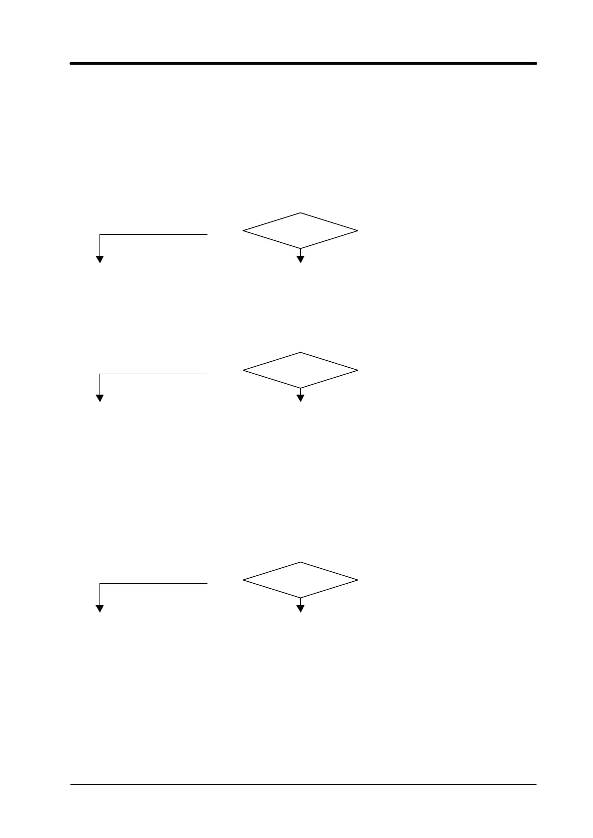
Correct?
♦ Correctly position the voltage changes.
♦ Remove any short-circuits on the transformer connections (79).
♦ Make sure that the bridge (78) is not short-circuited.
♦ Make sure that the remote switch (5) does not have stuck contacts, or that it is not
ordered to close before the capacitor (40) has been fully pre-charged and the
transformer (79) fully pre-magnetized.
♦ Mains not suitable to power the power source (ex.: insufficient installed power).
MAINS CONNECTION TEST.
q Mains input terminal board, terminals U1, V1, W1 = 3 x 230/400/440 VAC.
YES
NO
♦ Check power cable and plug and replace if necessary.
♦ Check the mains voltage conditions.
SERVICE TRANSFORMER POWER SUPPLY TEST.
q Fuse board (8), connector J6, terminals 0 - 230 = 230 VAC; connector J6 – 0 and connector
J5 – 400 = 400 VAC; connector J6 – 0 and connector J5 – 440 = 440 VAC.
YES
NO
♦ Check the wiring between mains input terminal board and J5 connector on board
(7) and between connector J6 on board (7), switch (60), and connectors J5 and J6
on board (8).
♦ Make sure the service voltage change is correctly positioned.
♦ Check fuse F1 on board (7); replace if broken, and make sure there is no short-
circuit in the service transformer (8) or corresponding wiring.
♦ Check switch (60); replace if defective.
♦ Service transformer (8) primary circuit interrupted.
CONTROL BOARD POWER SUPPLY TEST.
q Control board (62), connector J14, terminals 1 – 2 = 10 VAC.
YES
NO
♦ Check the wiring between J14 board (62) and J4 board (8).
♦ Check fuse F4 on board (8); if broken, replace and make sure that terminals 1 - 2
of J14 on board (62) are not short-circuited. If so, replace board (62).
♦ Check the 10 VAC voltage on terminals 0 – 10 of board (8); if missing, check the
wiring between the service transformer and board (8), or replace the service
transformer (8). If present replace board (8).
♦ Check the wiring between connector J11 on board (62) and the operator panel (64).
♦ Replace the operator panel (64).
♦ Replace board (62).