CEBORA S.p.A. 16
3.302.002 03/08/00
Correct?
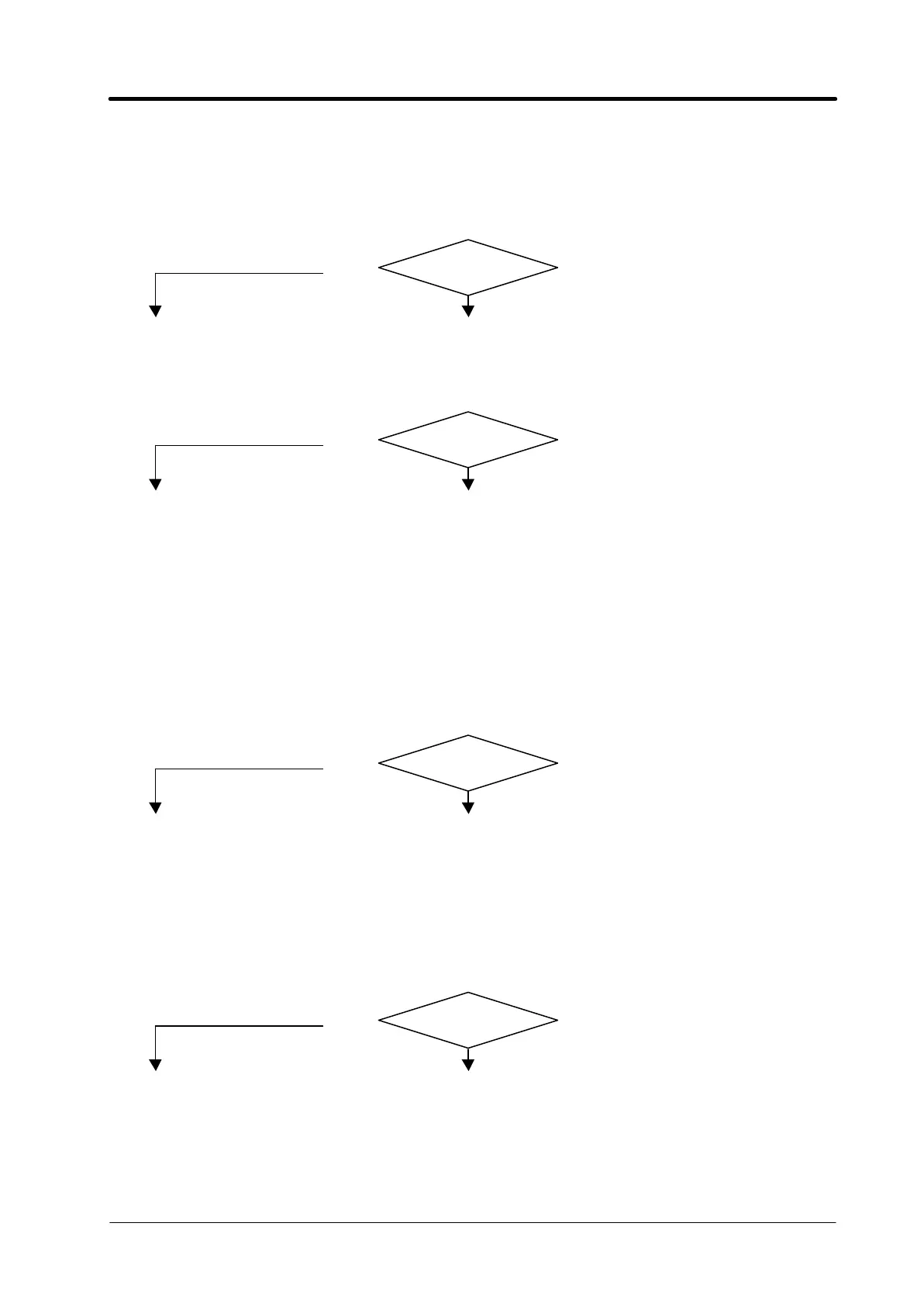
3.3.6 - Gas flows from the torch, pilot arc does not light (IGBT output voltage missing).
VOLTAGE TEST AT IGBT OUTPUT.
q Terminals 1 – 3 of IGBT (72) = 260 VDC with rated mains voltage, after pressing start
button and for a duration of 2 seconds (maximum pilot arc time).
NO
YES
♦ Go to par. 3.3.7.
DRIVER BOARD POWER SUPPLY TEST.
q Torch board (9), connector J1 terminals 1 – 2 = 18 VAC, terminals 5 – 6 = 20 VAC.
YES
NO
♦ Check the wiring between connectors J1 on board (9) and J2 on board (8).
♦ Check fuses F6 and F7 on board (8); if broken, replace and make sure that
terminals 1 - 2 and 5 - 6 of J1 on board (9) are not short-circuited. If so, replace
board (9).
♦ Check the 18 VAC and 20 VAC on terminals 0 - 18 and 0 - 20 of board (8); if
missing, check the wiring between the service transformer and board (8), or
replace the service transformer (8). If present replace the board (8).
DRIVER BOARD ENABLED TEST.
q Driver board (9), connector J3, terminals 1 – 2 = fig. 5.2.1 (pilot arc current set-point), after
pressing the start button and holding down for 2 seconds (maximum pilot arc time).
YES
NO
♦ Check the wiring between connectors J3 on board (9) and J2 on board (62).
♦ Make sure that terminals 1 - 2 of J3 on board (9) are not short-circuited. If so,
replace board (9).
♦ Replace board (62).
CURRENT TRANSDUCER TEST (71).
q Control board (9), connector J4 terminals 2 – 3 = +15 VDC and 2 - 1 = -15 VDC (power
supplies); terminals 2 - 4 = 0 VDC (current reaction, with power source started in stop).
YES
NO
♦ Check the wiring between current transducer (71) and connector J4 on board (9).
♦ Replace current transducer (71).
♦ Replace board (62).
♦ Check the wiring between connector J5 on board (9) and IGBT (72).
♦ Replace board (9).
♦ Replace IGBT (72).