Page 16 •
CEDIMA
®
• Technical Documentation • All rights reserved as per DIN 34 • „Subject to modifications due to progressive development“ •
Sect. 3 - Installation and Operator’s Controls of the Bench Saw
Bench Saw CTS•81, L, XL
Operating Manual 70 9998 0329 / UK 003
• Loosen the fixing screw securing the guide
block (fig. 3.4) and verify that the block is free
to move.
Attention: Always lock the guide block
prior to transporting the saw!
Use the fixing screw to lock the guide block befo-
re you transport the saw.
3.2 Notes relating to the electrical con-
nection
Attention: Observe the regulations con-
cerning electrical connections!
Work on electrical systems or equipment may on-
ly be carried out by electricians or trained staff
under the direction and supervision of an electri-
cian in accordance with the local electrical engi-
neering regulations.
For use on a construction site, the equipment
must be connected to the power supply in accor-
dance with DIN VDE 0100, § 55a.
The power outlet must be protected by an (FI or
DI) fault current breaker.
All electrical connections must be free of moistu-
re.
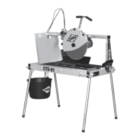
Figure 3.5 illustrates the power supply (230 V /
50 Hz) to the Bench Saw.
Fig. 3.5 Power Supply to the Bench Saw
Note: Check for possible power losses in
the supply cable!
When using a cable drum or a power supply ca-
ble, please observe the following:
• Never use a drum with the cable wound onto it
as this can cause loss of power at the machine.
• Do not exceed a cable length of 50 meters as
this can cause loss of power at the machine.
3.3 The mains switch
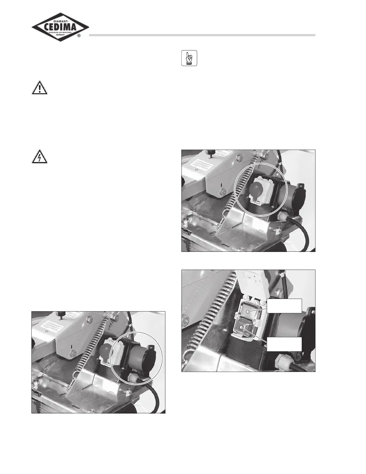
Fig. 3.6 Mains switch with emergency stop button
Fig. 3.7 ON and OFF button for starting and stopping
the saw
Red button
= OFF
Green button
= ON
The mains switch (fig. 3.6) switches the wet-pit
pump and blade drive motor on and off.
• To switch the pump and motor ON, open the
yellow lid with the red emergency stop button
and press the green button (fig. 3.7).