Page 18 •
CEDIMA
®
• Technical Documentation • All rights reserved as per DIN 34 • „Subject to modifications due to progressive development“ •
Sect. 3 - Installation and Operator’s Controls of the Bench Saw
Bench Saw CTS•81, L, XL
Operating Manual 70 9998 0329 / UK 003
• Problem: Electrical defect in the Bench Saw.
Remedy: Have the Bench Saw revised by a
qualified electrician.
3.6 Saw blade
3.6.1 Choosing the right type of saw blade
Attention:
Use only approved saw blades!
The blade shaft speed of the Bench Saw is exclu-
sively designed for cutting with diamond saw bla-
des. The Bench Saw may only be used for cutting
natural and artificial stone materials! Never use
the saw blades for cutting wood or metal.
The Bench Saws CTS•81 / CTS•81 L are designed
for the use of diamond saw blades with diameters
ranging from 350-400 mm. The CTS•81 XL is de-
signed for saw blade diameters not exceeding
350 mm. Saw blades with larger diameters must
not be installed on the Bench Saw.
The blade shaft speed of the Bench Saw is inten-
ded to provide optimum conditions for cutting
with
CEDIMA
®
diamond saw blades.
Choose the correct type of saw blade for the ma-
terial to be cut and the required cutting depth.
(Ask
CEDIMA
®
customer service for detailed
information on the right type.)
Note:
No guarantee in case of incorrect use!
Where
CEDIMA
®
diamond saw blades have be-
en used incorrectly, the guarantee becomes inva-
lid. Complaints concerning diamond saw blades
can only be entertained if at least 20% of the
height of the diamond segments remains.
Note:
Resharpen blunt saw blades!
Diamond saw blades are designed to be self-
sharpening in operation. However, they can be-
come blunt through frequent cutting in hard ma-
terial that is only slightly abrasive. Blades can be
resharpened by cutting in an abrasive material
such as chalky sandstone.
3.6.2 Installing the saw blade
To install the saw blade, proceed as follows:
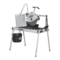
1. Loosen the knurled nuts (fig. 3.10) securing
the blade guard and remove the guard.
Fig. 3.10 Knurled nuts securing the blade guard
Knurled nuts
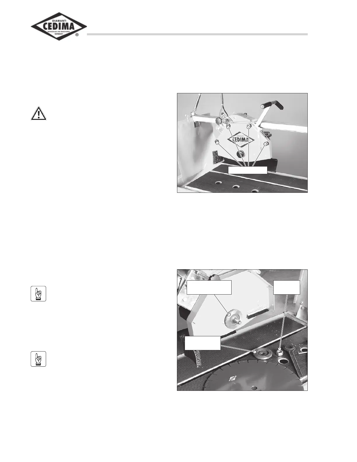
2. Loosen the cutting shaft nut from the blade
clamping flange using the open-jawed span-
ner and mandrel that come with the machine
(left-hand thread!)
3. Remove the blade clamping flange (fig.
3.11).
Fig. 3.11 Blade guard removed
Blade supporting
flange
Blade clam-
ping flange
Cutting
shaft nut