18
FI
FE
ENGLISH
Use and maintenance manual
6.4 STATIC UNBALANCE
The static unbalance is shown on display 1 and the relative correction position on the LED display 3
3
2
1
4
5
.The correction weight application diameter cannot be set, but is deduced from the
dimensions acquired in standard or ALU mode through interpolation algorithms and the use of fixed parameters.
Tolerance control is the same as for standard balancing, only that it refers to a single correction plane.
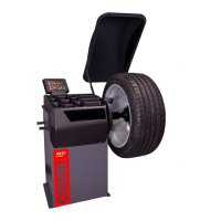
6.5 EXACT POSITIONING OF THE ADHESIVE WEIGHT BY MEANS OF THE GAUGE WITH CLIPS
▪ Press if using the correction method with adhesive weights on the inside of the rim
▪ Fit the correction weight in the specific gauge seat with the adhesive part facing upwards
▪ Bring the wheel into correct angular position for the plane to be corrected
▪ If the wheel clamp option is enabled (( MENU’) the wheel is automatically clamped in the correction position.
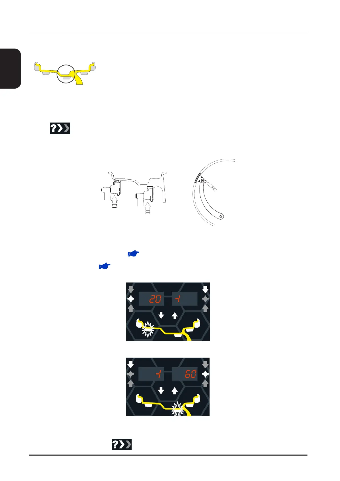
▪ Pull out the gauge until the leds 5 light up next to the correction weight.
If the buzzer is enabled ( MENU), the attainment of the weight application distance is accompanied by a
beep.
- INSIDE CORRECTION POSITION
- OUTSIDE CORRECTION POSITION
▪ Rotate the gauge until the correction weight adheres to the rim
▪ The fact that the weight application position is no longer vertical is automatically compensated.
To cancel the function, press the
button again.
Use of the wheel balancer