page 25 www.centsys.com
SECTION 7
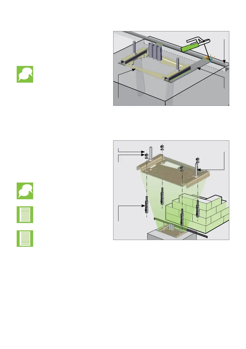
FIGURE 20
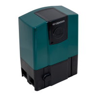
FIGURE 21
When using a concrete
foundation, it is
recommended that the
Foundation Plate is welded
to the rail/track of the gate
using a short length of at
bar, as shown in Figure 20.
This makes it possible
to complete the whole
mechanical and electrical
installation without having
to wait for the concrete to
set. After completing the
installation, the concrete
can be poured and the
operator left in Manual
Mode until the concrete
has set. Do not operate the
motor until concrete has
completely set.
Flat bar welded to
Foundation Plate
and rail
Foundation Plate
Rail
7.1.4.2. Existing Concrete Plinth
Nut
Washer
Mounting
Bolt
Expansion Stud
OPERATOR INSTALLATION
If bolting onto an existing concrete
plinth, place the Foundation Plate
down in the correct position and use
the plate as a template for marking
the Expansion Stud holes.
Rerouting of existing cables
may be necessary.
Ensure that the Expansion
Studs do not protrude more
than 23mm above the
Foundation Plate.
Check that the M10 half-
nuts are tightened to 20Nm
on the mounting bolts.
7.2. Retro-t Installations (Existing Sites)
The D10 SMART / D10 Turbo SMART has been designed to retro-t into existing D10
and D10 Turbo installations.
If the existing Foundation Plate is in a good condition, it is not necessary to replace
it with a new D10 SMART / D10 Turbo SMART Foundation Plate. However, if the
existing Foundation Plate is corroded or needs to be replaced for whatever reason,
the D10 SMART / D10 Turbo SMART Foundation Plate can accommodate the existing
footprint without the need to re-route cable conduits.
The D20 SMART is designed to t existing foundation plates for D10 and A10
installations. However, there are potential sites where an A10 was mounted high on a
foundation plate, and the D20 SMART will not be able to reach the rack.
In these cases, the rack will need to be lowered.