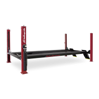
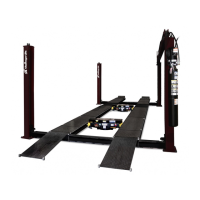
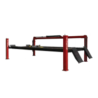
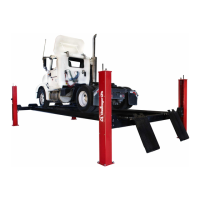
Model 4P14 Flat Deck, Closed Front
Installation, Operation and Maintenance
4 Rev 08/11/17
4P14-X-IOM-A.doc
Receiving
The shipment should be thoroughly inspected as
soon as it is received. The signed bill of lading is
acknowledgement by the carrier of receipt in good
condition of shipment covered by our invoice.
If any of the goods called for on this bill of lading are
shorted or damaged, do not accept them until the
carrier makes a notation on the freight bill of the
shorted or damaged goods. Do this for your own
protection.
NOTIFY Challenger Lifts AT ONCE if any hidden
loss or damage is discovered after receipt.
IT IS DIFFICULT TO COLLECT FOR LOSS OR
DAMAGE AFTER YOU HAVE GIVEN THE
CARRIER A CLEAR RECEIPT.
File your claim with Challenger Lifts promptly.
Support your claim with copies of the bill of lading,
freight bill, and photographs, if available.
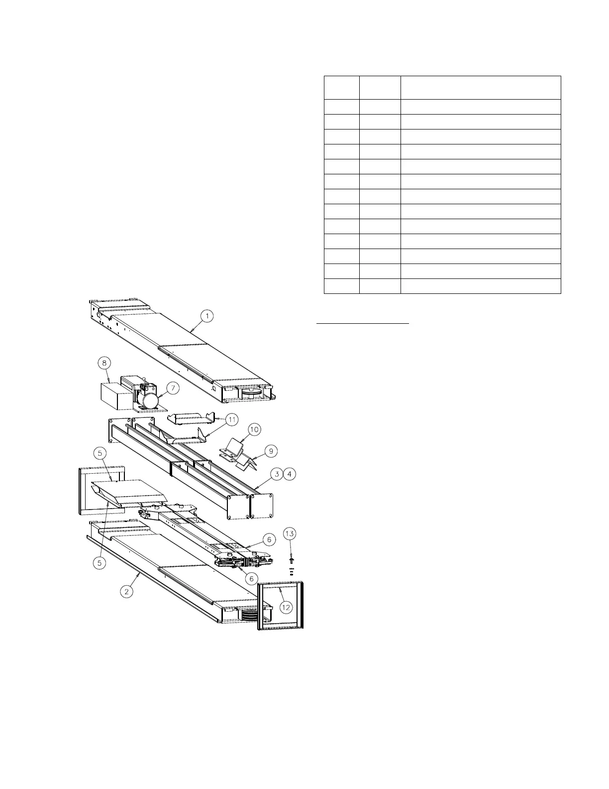
Fig 2 – Package Components
Component Packing List
ITEM
#
QTY/
LIFT
DESCRIPTION
1 1 IDLER RUNWAY ASS’Y.
2 1 POWER RUNWAY ASS’Y
3 1 POWER COLUMN ASS’Y
4 3 IDLER COLUMN ASS’Y
5 2 ENTRANCE RAMP WELD
6 2 CROSS BEAM ASS’Y
7 1 POWER UNIT
8 1 HARDWARE BOX
9 2 MOVABLE WHEEL CHOCK
10 2 FRONT WHEEL STOP
11 2 WORK STEP (alignment lifts only)
12 2 SHIPPING BRACKET WELD
13 8 ½” SHIPPING HARDWARE
INSTALLATION
IMPORTANT: Always wear safety glasses while installing lift.
TOOLS (MINIMUM REQUIRED)
a. Tape measure, 25ft
b. Chalk line
c. 4ft level
d. 10” & 12” adjustable wrench
e. Standard open end wrenches 3/8”, 7/16”, 1/2",
9/16”, 5/8”, (2) 11/16”, 3/4", 15/16”, 17mm
f. 6mm allen wrench
g. Box knife
h. Thread locking compound
i. Thread tape sealant (for air line)
j. Needle nose pliers
k. Hammer drill with 3/4” diameter carbide tipped
bits
l. 2lb hammer
m. Torque wrench: 150 foot pounds minimum with
1 1/8” socket
n. 8 ft. Step ladder
o. Blocking – (4) 4x4x30”, (4) 1x4x12”
p. Transit for leveling alignment lift
L
AYOUT
1) Lay out the service bay according to the
architect’s plans or owners instructions, Fig 1.
Be certain that the proper conditions exist, see
page 3.
2) Unpack lift. Remove all packaging from Power
Runway (power runway has four cable sheaves
at rear end) and pull threaded cable ends out.
Make sure the cables are in the proper sheaves
at the 4-stack, Fig 3.