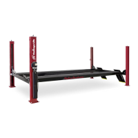
Model 4P14 Flat Deck, Closed Front
Installation, Operation and Maintenance
8 Rev 08/11/17
4P14-X-IOM-A.doc
31) BE CERTAIN ALL FITTINGS AND CONNECTIONS
ARE
TIGHT. IT IS THE INSTALLERS
RESPONSIBILITY TO INSURE SYSTEM IS LEAK
-
FREE. Fill the Power Unit with three gallons of
clean 10wt anti-foam anti-rust hydraulic oil or
Dexron III ATF. D
O NOT USE OILS WITH
DETERGENTS.
32) Energize the power unit and raise the lift
approximately 1 ft off the ground and look
underneath the power runway to verify that
the cable lugs are resting firmly against the
cylinder pull bar.
33) Level the runways and crossbeams using a 4
ft. level. With the lift resting in its locks, find
the highest corner and adjust the other three
column ladder bars until the runways are
level front-to-rear and side-to-side. Tighten
jam nut against bottom side of each column
top plate.
34) Adjust cables until all four locks are
synchronized when lift is raised. Tighten
cable jam nuts against adjustment nuts.
35) Install 4mm air line from air valve assembly
thru opening in runway to Tee fitting. Fig 12.
FRONT
4mm AIR LINE
4mm TEE
POWER UNIT
w/ AIR VALVE
ASS'Y
REAR
4mm TEE FACTORY
INSTALLED AT EACH
CROSS BEAM END
4mm SPLICE
4mm TEE FACTORY
INSTALLED AT EACH
CROSS BEAM END
FRONT
4mm TEE
4mm SPLICE
POWER UNIT
w/ AIR VALVE
ASS'Y
4mm AIR LINE
REAR
4mm TEE FACTORY
INSTALLED AT EACH
CROSS BEAM END
FRONT
4mm TEE
4mm SPLICE
POWER UNIT
w/ AIR VALVE
ASS'Y
4mm AIR LINE
REAR
4mm TEE FACTORY
INSTALLED AT EACH
CROSS BEAM END
FRONT
4mm TEE
4mm SPLICE
POWER UNIT
w/ AIR VALVE
ASS'Y
4mm AIR LINE
REAR
Fig 12 – Lock Release Air Line Routing
36) Route power side front and rear cross beam
air lines through power runway to Tee fitting.
Route idler side front and rear cross beam air
lines through idler runway and connect
together with 4mm air line splice provided.
Route airline through welded rings on the
outside internal edge of runways.
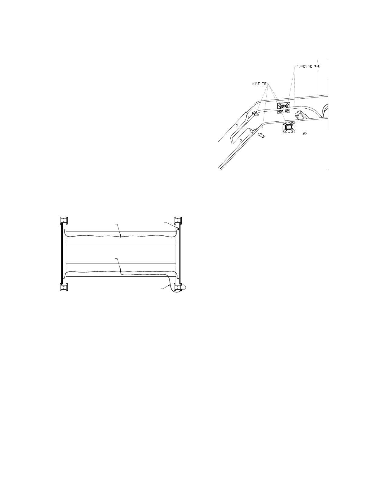
37) Use the provided wire ties and adhesive tabs
to connect the 4mm air line inside the ends of
the front and rear cross beam to the side
plate welds as shown in Fig 13.
Fig 13 – 4mm Air Line Connection
38) Use the hose barb and clamp provided to
connect the button valve to a suitable air
source. Air supply must be clean, dry,
lubricated, and regulated to 90-120 psi.
The FRL, must be within 30 feet of valve.
Failure to provide clean, dry, lubricated,
and pressure regulated air will void
warranty on pneumatic components.
39) Energize air valve assembly and insure that
all air cylinders are working properly.
40) Raise and lower lift several times to bleed
hydraulic cylinder. Hydraulic cylinder is self-
bleeding. Lower lift and check fluid level in
reservoir. Add fluid as needed.
41) Run lift to full rise and continue running motor
approximately 5 more seconds. Check
hydraulic hose and connections for leaks.
Re-tighten fitting if leaking.
42) Raise lift approximately half way. Slowly jog
power unit until you hear one of the locks
engage. Adjust locking ladder until it just
barely raises the crossbeam end. Back off
1/2 turn. Repeat for each column.