Model 4P14 Flat Deck, Closed Front
Installation, Operation and Maintenance
5 Rev 08/11/17
4P14-X-IOM-A.doc
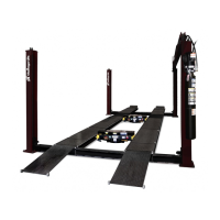
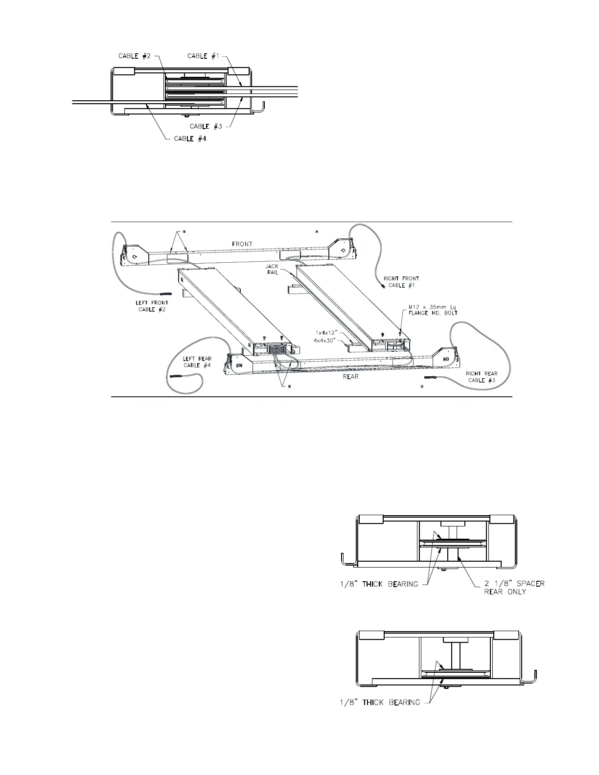
Fig 3 – Power Runway 4-Stack (rear view)
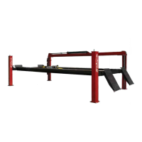
3) Position runways on blocking (see Fig 4) per
layout lines established in step 1. Use four 30”
long 4x4’s spanning the width of the runway and
four 12” long 1x4’s to shim up the jack-rail side
of the runway. Cable #1, #3, & #4 should be
extending out from the rear of the power runway
and cable #2 from the front of the power runway,
Fig 4.
4) Position the front and rear cross beams, Fig 4.
(Both cross beams are identical.)
5) Reach in through either of the access holes in
the cross beam tube and pull out the roll of 4mm
dia. plastic air line connected to the air cylinder
at the end of the cross beam. Repeat for
opposite access hole and position the cross
beam near the end of the runways as in Fig 4.
POWER RUNWAY MUST USE OUTER SET OF HOLES
POWER RUNWAY MUST USE OUTER SET OF HOLES
POWER RUNWAY MUST USE OUTER SET OF HOLES
POWER RUNWAY MUST USE OUTER SET OF HOLES
POWER RUNWAY MUST USE OUTER SET OF HOLES
POWER RUNWAY MUST USE OUTER SET OF HOLES
POWER RUNWAY MUST USE OUTER SET OF HOLES
POWER RUNWAY MUST USE OUTER SET OF HOLES
Fig 4 – Runway Layout
6) Remove the four (4) cross beam sheaves
(one sheave from each end) and the two idler
runway sheaves (also one sheave from each
end). The runway sheave pins do not need
to be removed, just lowered enough to
remove the sheaves.
7) Starting from the bottom of the sheave stack,
route cable #4 through the access hole and
up out the left end of the rear beam. Repeat
for cable #3 out the right end of the rear
beam. Route cable #1 through the access
hole, and back out the idler side access hole.
Look through the idler end of the cross
beam and ensure that cable #1 and #3
have not crossed.
8) Route cable #1 through the idler runway, into
the front cross beam access hole, and out
the right end of the front beam. (Don’t forget
to route it up over the cross-braces in the
bottom of the runway.)
9) Route left front cable #2 through the access
hole and up out the left end of the front
beam.
10) Reinstall the cross beam sheaves with one
plastic bearing washer on each side of each
sheave.
11) Reinstall the idler runway sheaves, with one
plastic bearing above and below each
sheave per figures 5 & 6. Note: use one
2 1/8” long spacer at the idler rear sheave
only.
12) Confirm that a 2 1/8” spacer is installed at the
rear of the idler runway and none at the front
of power or idler runways.
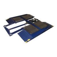
Fig 5 – Rear
Single-Stack (idler runway)