Model 4P14 Flat Deck, Closed Front
Installation, Operation and Maintenance
6 Rev 08/11/17
4P14-X-IOM-A.doc
Fig 6 – Front Single-Stack (typical for idler and
power runways)
13) Attach both cross beams to the runways
(Fig. 4) with M12 x 35mm lg. flange head
bolts (two at each end of each runway) being
careful not to pinch the air line. Leave the air
lines hanging out the bottom of the cross
beam access holes at this time, they will be
fed in through the runway after the lift is
raised. The outermost power runway slots
should be in line with the outermost holes
in the top of the cross beam, see Fig. 4.
The idler runway can be installed using the
outer or inner sets of cross beam holes, see
“Width Between Runways” dimension in
Fig. 1. Do not torque bolts yet.
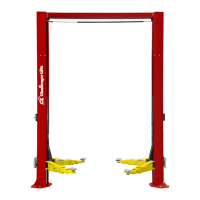
14) Check the layout of the lift in the bay. (This
is the last opportunity to reposition the
lift.) Adjust the position of the runways so
the distance from power side jack rail to idler
side jack rail is the same at the front and the
rear and the diagonal measurements from
the front tip of one rail to rear tip of the
opposite rail are within 1/4”, Fig 7.
SIDE TO SIDE TO BE IDENTICAL
DIAGONALS TO BE WITHIN 1/8"
SIDE TO SIDE TO BE IDENTICAL
DIAGONALS TO BE WITHIN 1/8"
SIDE TO SIDE TO BE IDENTICAL
DIAGONALS TO BE WITHIN 1/8"
SIDE TO SIDE TO BE IDENTICAL
DIAGONALS TO BE WITHIN 1/8"
Fig 7 – Final Runway Positioning
15) Center cross beam bolts with slots in runway
and tighten. (Be careful not to move
runways.)
C
OLUMNS
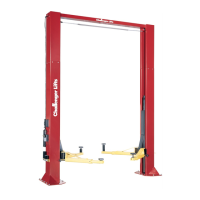
16) Stand up a column assembly near each
corner of the lift (column with power unit
bracket goes at the 4-sheave-stack corner,
power rear) and check the locking ladder bar
orientation per Fig 8. Note that the center of
the threaded rod is offset (away from the
back of the column) from the center of the
ladder. Thread the locking ladder jam nut
(located under the column top plate) down
approximately 6” to allow the ladder to be
lifted freely.
THREADED
ROD
LADDER
BAR
LOCKING
Fig 8 –
Locking Ladder Orientation
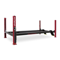
17) Slide power side column onto cross beam
until the M8 threaded holes in the side of the
beam are just exposed. Position slide blocks
as shown in Fig 9 and attach with M8 x
16mm lg. bolts (apply thread locking
compound before installing).
Fig 9 – Slide Block Installation
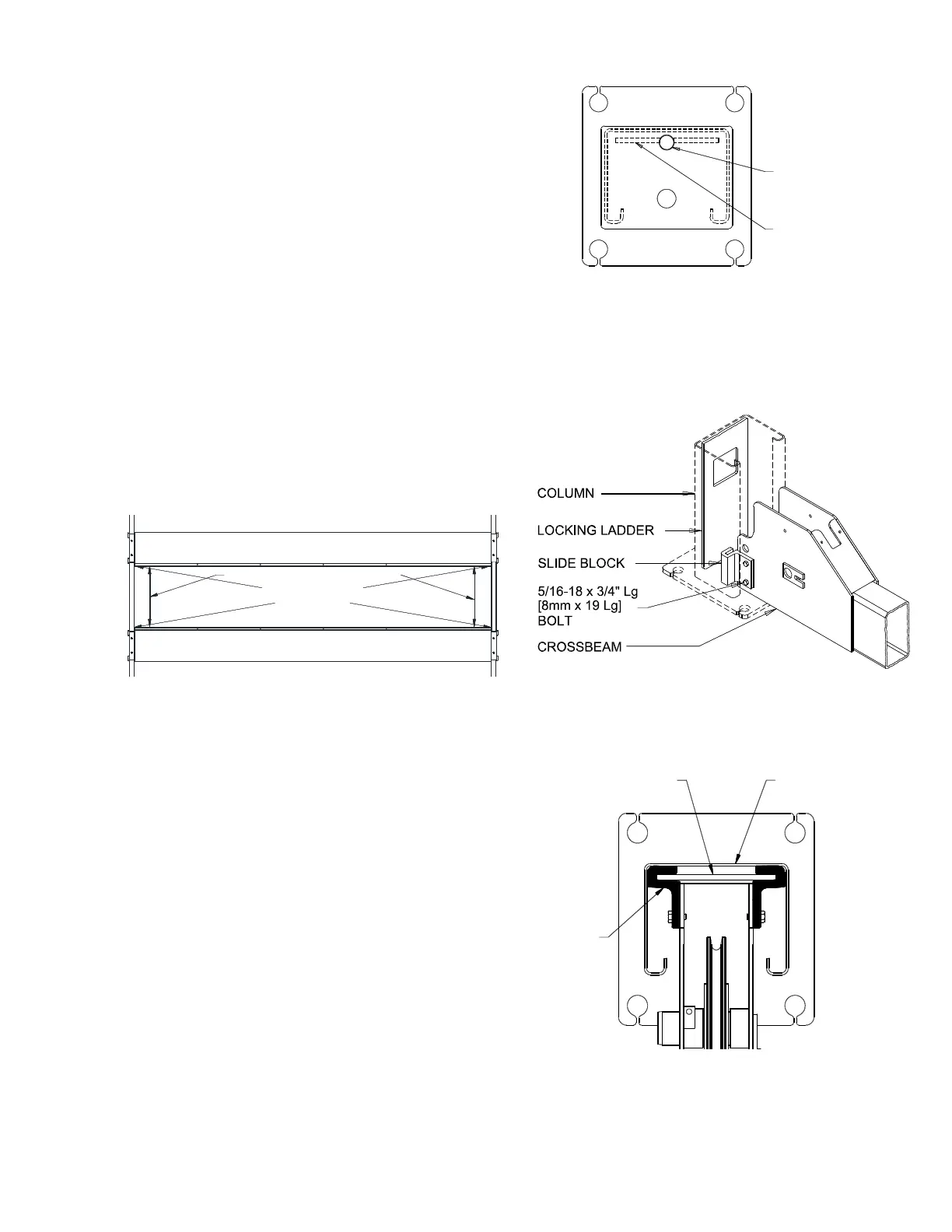
18) Raise the locking ladder, push the column
against the slide blocks, and lower the ladder
into the slide blocks, Fig 10.
COLUMN
LOCKING
LADDER
SLIDE
BLOCK
COLUMN
SLIDE
BLOCK
LOCKING
LADDER
COLUMN
SLIDE
BLOCK
LOCKING
LADDER
COLUMN
SLIDE
BLOCK
LOCKING
LADDER
Fig 10 – Locking Ladder Orientation
19) Repeat for remaining three columns.
A
NCHORING