Model 4P14 Flat Deck, Closed Front
Installation, Operation and Maintenance
7 Rev 08/11/17
4P14-X-IOM-A.doc
20) The anchor bolts must be installed at least 8”
from any crack, edge, or expansion joint.
21) Use a concrete hammer drill with a 3/4 inch
carbide bit. Tip diameter should conform to
ANSI Standard B94.12-1977 (.775 to .787).
Do not use excessively worn bits or bits
which have been incorrectly sharpened. A
core bit may be necessary if an obstruction is
encountered. Never substitute with shorter
anchor.
22) Drill the anchor holes using the base plate as
a template. Drill through the floor if possible
or to a depth of 5 inches minimum.
23) Vacuum dust from the hole for proper holding
power.
24) Shim columns to plumb using the shims
provided or steel washers. DO NOT shim
more than 1/2" at any given point. Use a level
no less than 24” in length to plumb columns.
25) Assemble washer and nut to anchor with nut
just below impact section of bolt. Drive
anchor into hole until nut and washer contact
base. Tighten anchor bolts and recheck
column for plumb. Re-shim as required.
26) Torque to 150 foot-pounds to set anchors.
NOTE: Level bubble should not only be
between the lines, the bubble should be
centered
between the lines. If the provided
shims do not allow sufficient centering of the
bubble, it is best to lean the rear columns in
the direction toward each other and the front
columns in the direction toward each other.
27) Install the four cable ends with one flat
washer, one load nut, and one jam nut.
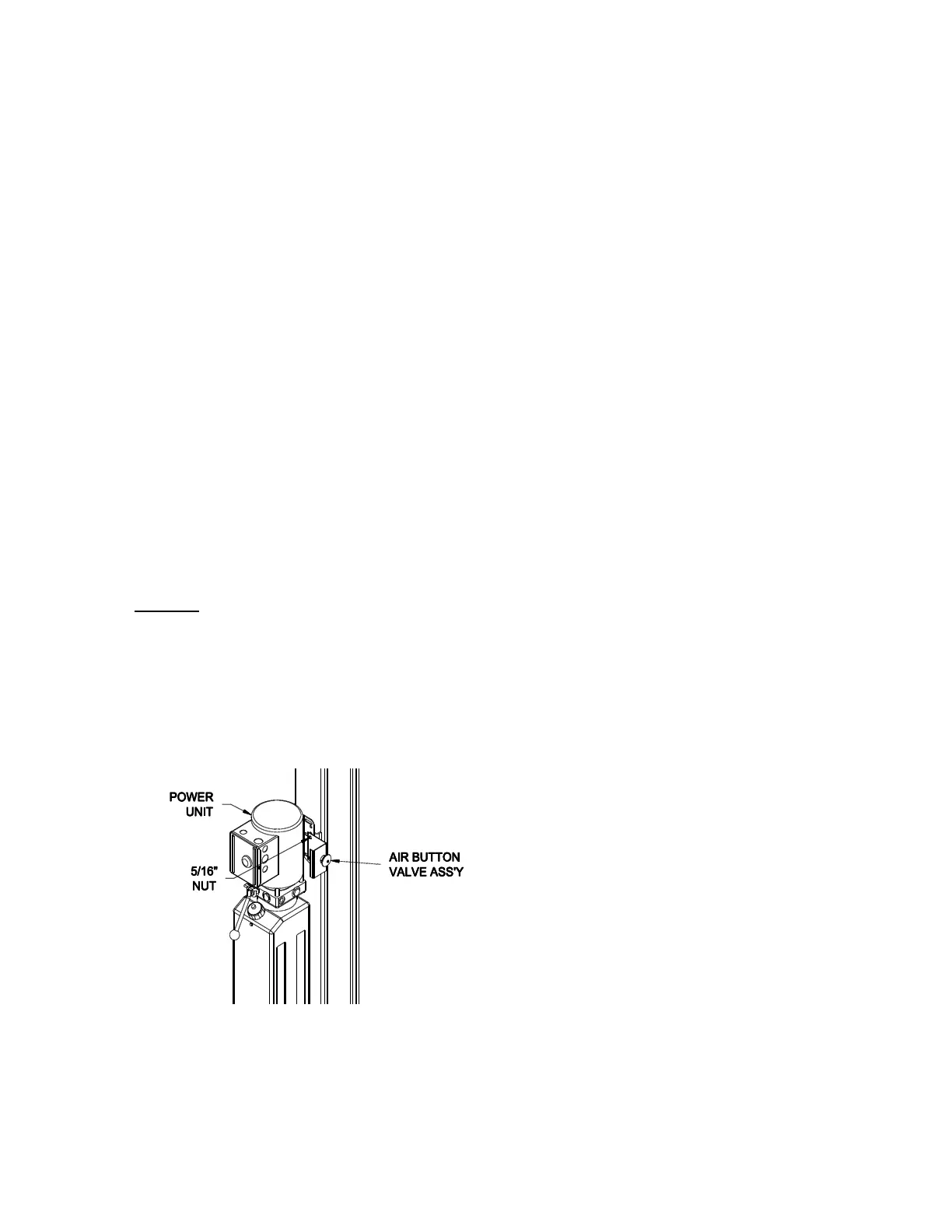
28) Install the power unit and the air button valve
assembly on the power column, Fig 11.
Fig 11 –
Air Button & Power Unit Mounting
29) Install O-Ring end of 90 degree hydraulic
elbow (9/16-18 O-Ring x 37 Male JIC) to
power unit output port. The hydraulic hose is
pre-installed to the hydraulic cylinder and
secured inside the runway. Pull loose end
out through 1 ½” x 4 ½” slot in the side of the
power runway near the power unit and attach
to the elbow fitting.
Do Not Use Teflon Tape or Pipe Dope on
fittings.
30) Have a certified electrician connect the
power unit to a suitable electrical power
source as shown in Fig 16.