51
NOTES:
1) These distances are for accessory wires such as 3-button control stations, photo-eyes, loop detectors and treadle
hoses.
2) The control distance is the distance between the power connection and the accessory in question.
e.g. a 3-button control station 25 feet from the operator
a loop detector 30 feet from the operator
photo-eyes 10 feet from the operator
Main Power Wire Gauge And Length Recommendations
A power drop between idle (off) and running voltage should not exceed 2 volts.
Understand the amperage rating for each operator’s voltage and horsepower using Table 1. The information in the
table may change without notice; review the instruction manual provided with each operator for the most current
information.
Determine the gauge of wire needed to safely accommodate the distance between the operator and the electrical box
using either Table 2A for SINGLE PHASE or 2B for THREE PHASE (page 51).
NOTES:
1) The amount of electricity carried by a wire is restricted to the release of heat through the electrical insulation
material (the cable insulation can melt if the improper gauge is used).
2) Don’t run control wiring and power wiring in the same conduit, these wirings should be separated by 18”.
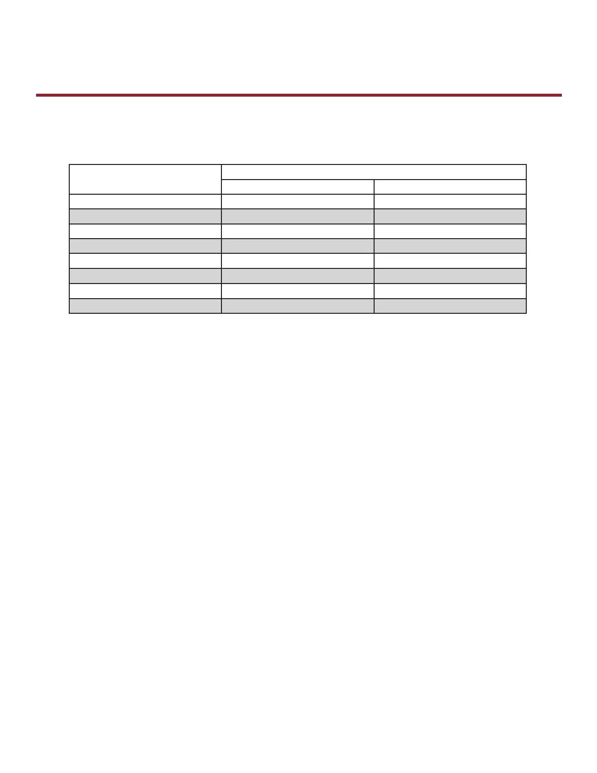
Recommended Control Wire Gauge Based On Wire Run Length For Mechanical Operators
Logic Operators are rated for up to 1000 feet with 18-gauge wire.
Wire Gauge
(AWG)
Control Wire Distance
MECHANICAL LOGIC
Feet Feet
22 N/A 600
20 50 700
18 75 1000
16 115
14 180
12 290
10 500
E
General Information
Recommended Wire Gauge Chart
 Loading...