D10.D15.DRS15-MANS
Apr ‘19
- 10
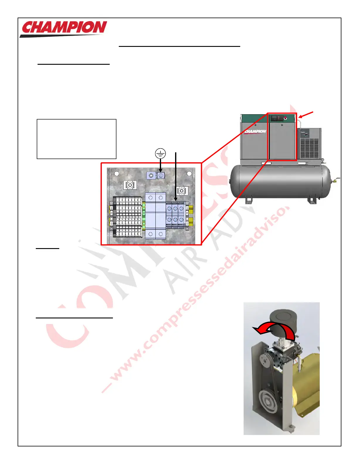
The Electrician is to bring power to the Unit through the ¾” conduit hole located on the Right
Panel. The Electrical Panel is accessible by means of opening the Unit Front RH Panel as
shown at right.
3 terminal blocks are provided for main power hook-up
Installation – Electrical (cont’d)
Wiring must be done in a manner that the full Motor nameplate voltage +/- 5% is available at the Motor terminals
during start-up. Contact your local Distributor or Service Centre if additional information is needed.
The Warranty that exists on the Electric Motor is that of the original manufacturer. In the event of a Motor failure,
locate a certified EISA motor service centre.
It is critical that the Motor and Air End in the Rotary Screw Unit be turning
in the correct manner. Irreparable damage will be done if the Unit rotates
in the opposite direction.
This unit is equipped with Advanced Phase Detection which prevents unit
from rotating in the reverse direction. If the following error is visible on the
Screen and the Unit will not start, simply switch power leads L1 and L3.
Press the ‘Reset’ key on the Controller to reset the error message.
E:0090 Phase Sequence
Note: If the Motor is replaced or Motor Leads are re-wired,
visually check for correct Motor Rotation before installing
the belts.
Electrical Connection
Motors. Motors
Motor/Air End Rotation
Bring power to
Terminal Blocks
L1, L2, L3
Conduit
Opening
Protective
Earth
Connect ground wire to
Protective Earth terminal.
Bring power to L1,L2,L3.
See page 12 for start-up
procedures
 Loading...