CAC Gasoline Engine Maintenance And Servicing Manual
51
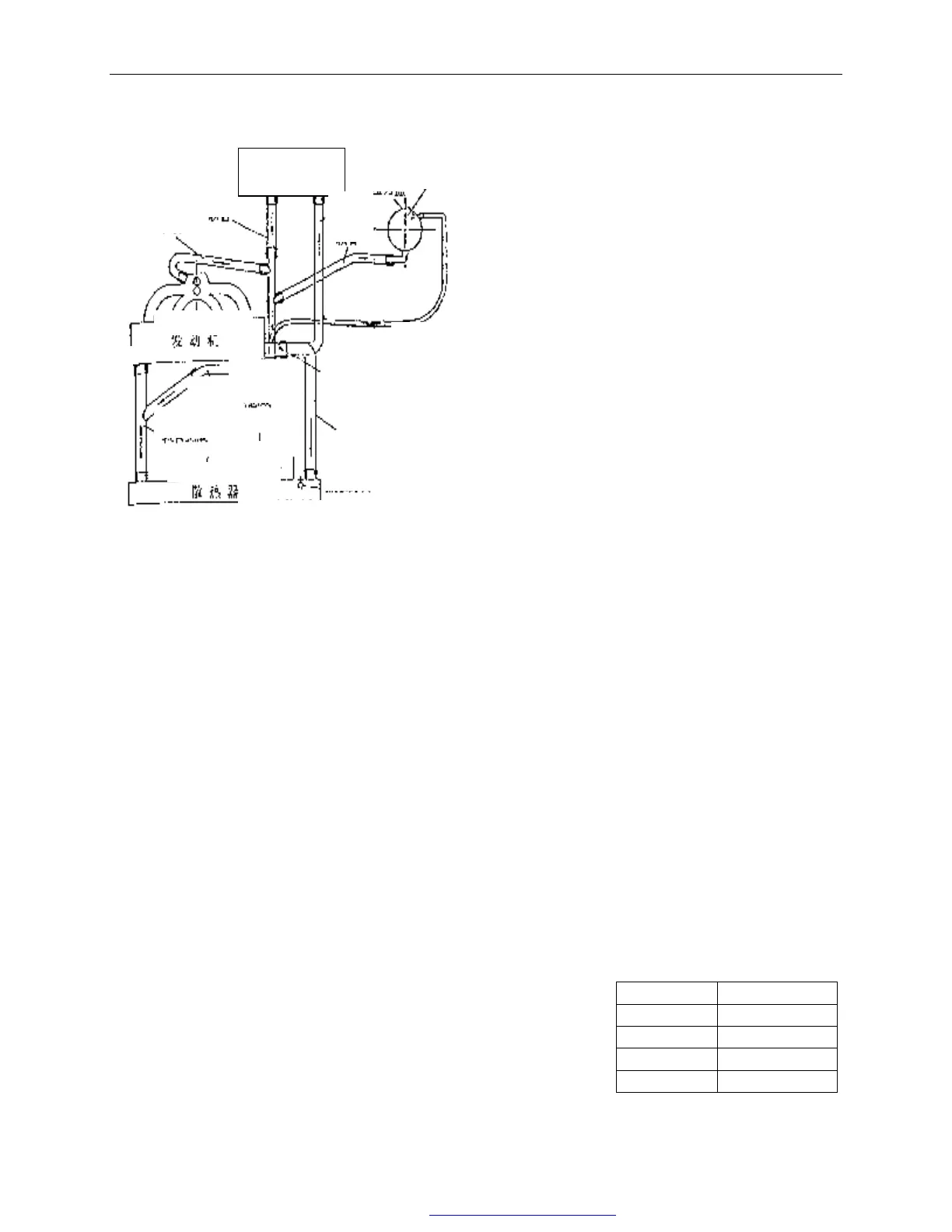
【14】 Engine cooling system
1) Description for cooling system
The cooling system is of pressure system. It
includes water pump driven by timing belt,
crosscurrent radiator, expansion tank, pressure
cap, thermostat and electric fan, fan shroud.
When engine coolant temperature is low,
water pump draws the coolant in the left water
room of radiator and pump it to the cylinder
block, cylinder head and intake manifold after
pressurizing, going from the local circulation
pipe of the thermostat seat to the warm air
heat exchanger, and then from heat exchanger
back to water pump inlet. The coolant back
from intake manifold joins the heat exchanger
and then backs to water pump inlet.
When engine coolant temperature reaches the
point for thermostat to open, the coolant for
cooling cylinder block, going through the
opened thermostat , combusting chamber and
behind the valve seat , will go into the right
water room of radiator from the drain pipe
of thermostat seat. For being cooled by
electric fan blowing ,the coolant is already
cooled When it reaches the left water
room,.
When engine works under normal working temperature, coolant will expand. so the relief valve in the
thermostat seat opens. The coolant enters the expansion tank from overflow tube. After the system is cooled,
the coolant comes back to the inlet of water pump from expansion tank.
The electric fan operation is controlled by thermo switch installed in the right water room of radiator.
When the contactpoint of thermo switch closes, the electric fan operates. Water temperature sensor is at the
back of the cylinder head at exhaust pipe side.
—cooling system parameters:
total system capacity (L)8 electric fan water pump
engine capacity(L)3.3 diameter. 280mm diameter. of impeller
72mm
radiator capacity(L)2.1 blade quantity 6 speed ratio 1.053∶1
expansion tank capacity(L)0.4 operating voltage 9-16V pressure cap
RPM GradeⅠ 1500r/min operating pressure
160kPa
radiator Grade Ⅱ 2800r/min water temperature sensor
front face area 0.202 ㎡ thermo switch
radiation area 8.93 ㎡ operating temperature
GradeⅠ95 ℃
thermostat GradeⅡ102±3℃
opening temperature 85°-89° cut off temperature
GradeⅠ≤84℃
resistanceΩ
temperature℃
70
159±21.3
90
86.7±11
110
52.3±6.3
124
28.2±2.8
-3
hose
exchanger
hose
hose
cap
hose
engine
carrier
regulator assembly
water
sensor
coolant
pipe
assembly
assembly
switch
Fig. 93
PDF 文件使用 "pdfFactory Pro" 试用版本创建 www.fineprint.com.cn