Maintenance Manual for Chery·Windcloud Marelli EFI System
8. Electromagnetic Injector
Purpose: according to ECU instruction,
injector ejects fuel within the stipulated time,
by which means providing engine with fuel
and atomizing it.
Composition and principle: ECU sends out
electric impulse to injector coil, forming
magnetic field force. When the magnetic
field force increases well enough to
overcome resultant force of retracing spring
pressure, pin valve gravity and friction, pin
valve starts to lift, and the fuel injection
begins. The maximum lift range of pin valve
shall not exceed 0.1mm. In case fuel
injection impulse is cut-off, the pressure of
retracing spring enables pin valve to switch
off again.
Installation hints: a certain injector shall
apply to a certain pin without mixing use.
In order to facilitate installation, it is
recommended to apply uncontaminated
silicon-free engine oil to the surface of
upper O-ring connecting with fuel
distributing pipe. Be careful not to let engine
oil contaminate interior or squirt hole of
injector.
Install injector into injector seat in the
direction perpendicular to the seat, and then
fix the injector on it with clamp. No
discontinuous resistance shall be felt when
rotating injector manually.
Caution: for long-term idle vehicle,
gasoline cementation in injector results in
failure of normal startup of vehicle after
long-term idling. In this case please check
carefully to see if the injector cements, and
check atomization as well
Failure diagnosis: EFI system of A11 does
not apply failure diagnosis to injector itself,
but to injector driver stage. When the driver
stage of injector is in short circuit or excess
load status to accumulator, in short circuit
and open circuit status to ground, the failure
mark is set. At this point, shut down oxygen
sensor closed-loop control and its
self-learning precontrol, the last
self-learning data is valid. After
troubleshooting, failure mark restores.
Working pressure: 350 kPa
Injector resistance: 13.8 -15.2± 10%
Working temperature: -30°C - +110°C
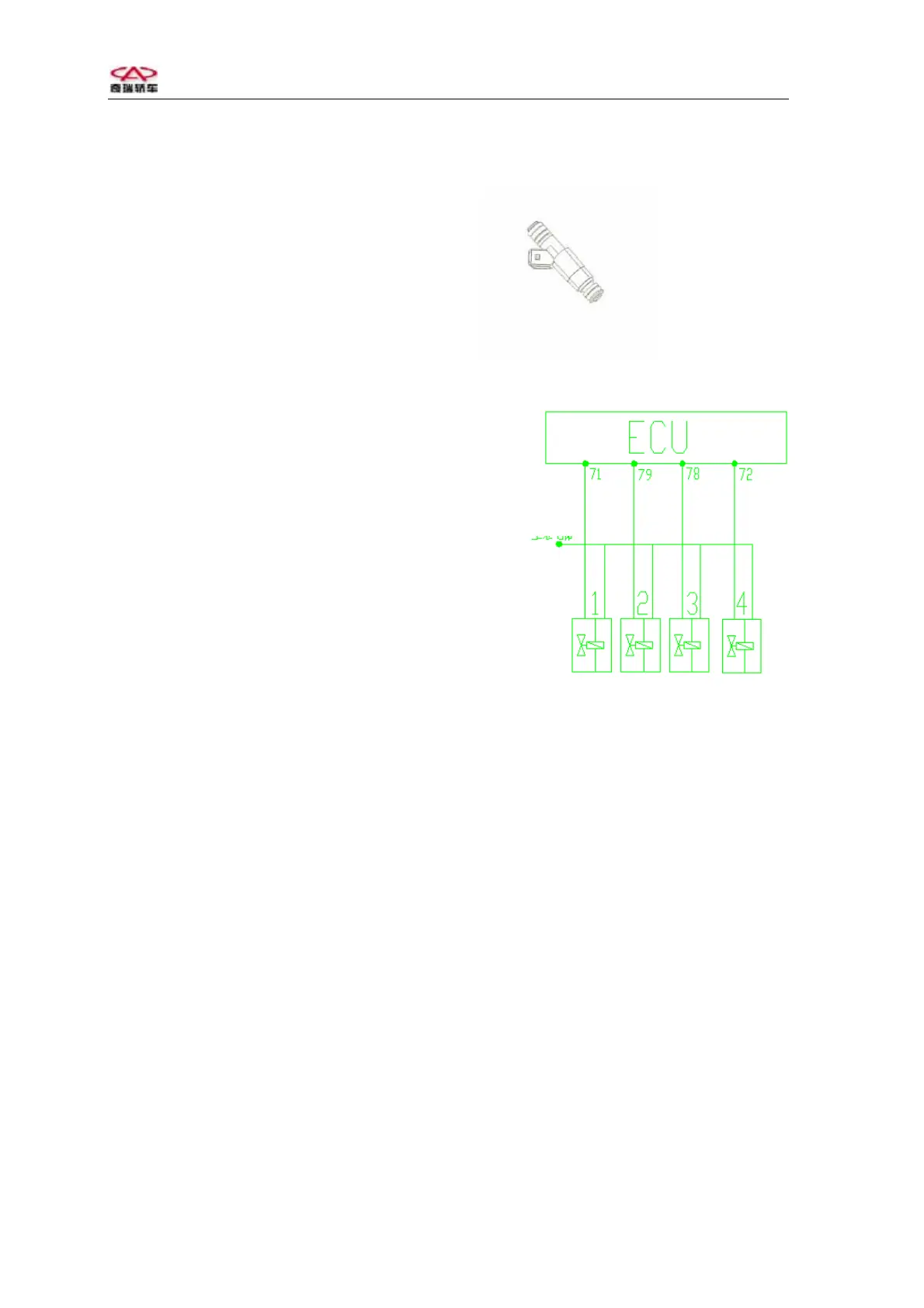
Electromagnetic injector
Main power
Circuit diagram of electromagnetic injector
Pins: each injector has 2 pins. Of which, the
one marked with positive sign beside
housing shall be connected with 87# pin of
fuel pump relay output terminal; the other
shall be connected with 71#, 79#, 78# or 72#
pin of ECU respectively. Grounding
(injection pulse width) is controlled by
ECU.
Troubleshooting: generally injection
nozzle’s non-smooth fuel injection and
defect atomization is caused by long-term
application of engine. To solve this
problem, periodical cleaning of injection
nozzle is required.
Short circuit, open circuit in interior coil of
injection nozzle may also result in fuel
injection system failure.
Check to see if there is short circuit or open
circuit in system line (between injectors
and ECU 71, 79, 78, 72 pins).
9