Maintenance Manual for Chery·Windcloud Marelli EFI System
13. Rotational Speed Sensor
Purpose: rotational speed sensor provides
engine ECU with rotating speed, rotating
angle and reference signals for control of
engine cylinder detection and ignition;
rotational speed sensor of induction type
combines with oscillator to provide engine
speed information and crankshaft top dead
center information in the distributor-less
ignition. Rotational speed sensor of
induction type is made up of a permanent
magnet and coils wound on magnet.
Oscillator is a fluted disc with 60 teeth
originally, except for 2 vacant teeth. It is
installed on crankshaft and rotates with it.
When tooth point passes from next to the
end of rotational speed sensor of induction
type, oscillator made from ferromagnetic
material cuts magnetic force lines of
permanent magnet of the aforesaid sensor,
generating induced voltage and outputting as
rotating speed signal.
Composition and principle: This vehicle
adopts rotational speed sensor of magnetic
pulse type, with coils winding around a slug
inside, signal wheel rotating at high speed
and cutting magnetic lines of force; induced
electromotive force is generated in coils,
while ECU, according to the frequency of
the said force generated, calculates engine
rotating speed for the use of engine control.
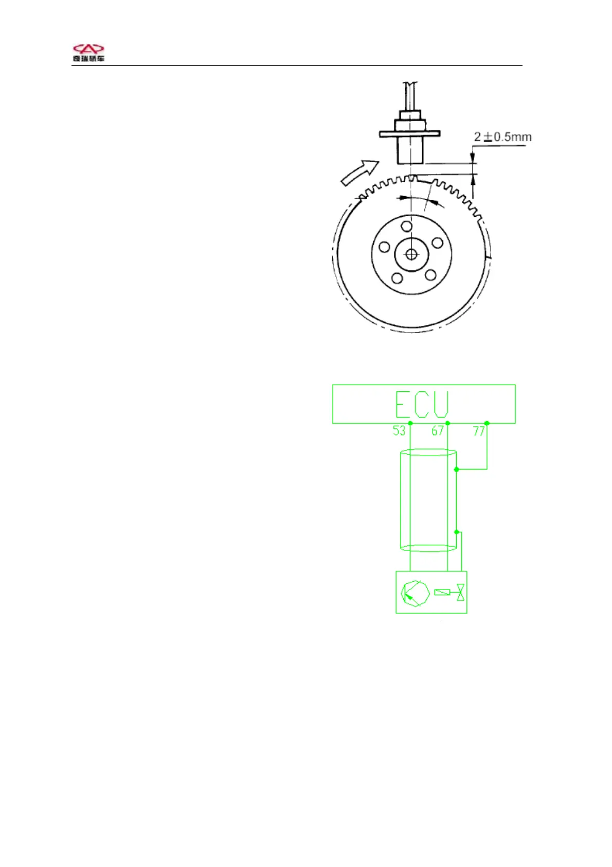
Installation requirement: clearance 20.5
mm (nonadjustable)
Coil resistance: 1150-1400 ohm
Failure diagnosis: engine ECU will identify
failure of crankshaft position sensor in case
that any of the following conditions occurs
in sensor:
Sensor line short circuit to ground;
Sensor line open circuit;
Sensor signal distortion.
After failure of rotational speed sensor is
identified, engine will not be started, and
fuel pump relay will not be ON.
Troubleshooting: check to see if sensor line
is normal;
Check to see if resistance in sensor is
normal;
Check if shielded line circuit is open.
Assembling schematic drawing for
crankshaft position sensor
Engine rotational speed senso
Circuit diagram of rotational speed sensor
Pins: Pin 1 connecting with ECU’s 53# pin
(signal +)
Pin 2 connecting with ECU’s 67# pin
(signal -)
Pin 3 connecting with ECU’s 77# pin
(shielded line)
14