Maintenance Manual for Chery·Windcloud MOTOROLA EFI System
1
Chapter One: Operating Principle for EFI
Control and Execute Components
1. Intake Pressure and Intake Air
Temperature Sensor
MOTOROLA EFI system adopts air
measurement method of velocity and density to
measure the air capacity entering engine so as
to control fuel injection pulse width further
accurately control engine power output.
Pressure-sensitive element inside intake
pressure sensor detects pressure signal on
intake manifold via sensing hole connecting
intake manifold, within which is a
pressure-sensitive element, the resistance value
varies with the changing pressure, after
conversion of this signal, it will become an
important parameter for the control of engine
performance.
Intake air temperature sensing element is a
resistor of negative temperature coefficient
(NTC), which is similar to water temperature
sensor with resistance value decreasing with
the increasing of intake air temperature. And
engine ECU monitors the variation of intake air
temperature via a comparison circuit inside.
Failure diagnosis:
Short circuit occurs on the sensor line circuit;
Open circuit occurs on the sensor line circuit;
Sensor detects intake pressure to be over upper
limit;
Sensor detects intake pressure to be over lower
limit;
Installation: to be installed on pressurizer.
Troubleshooting: mainly check if there is
short circuit or open circuit on the connection
between 4 lines on senosr and ECU.
If sensor’s sensing hole is pluged up.
If there is short circuit, open circuit or
grounding between sensor wire harnesses.
Manifold absolute pressure /intake air temperature sensor
Intake temperature
pressure sensor
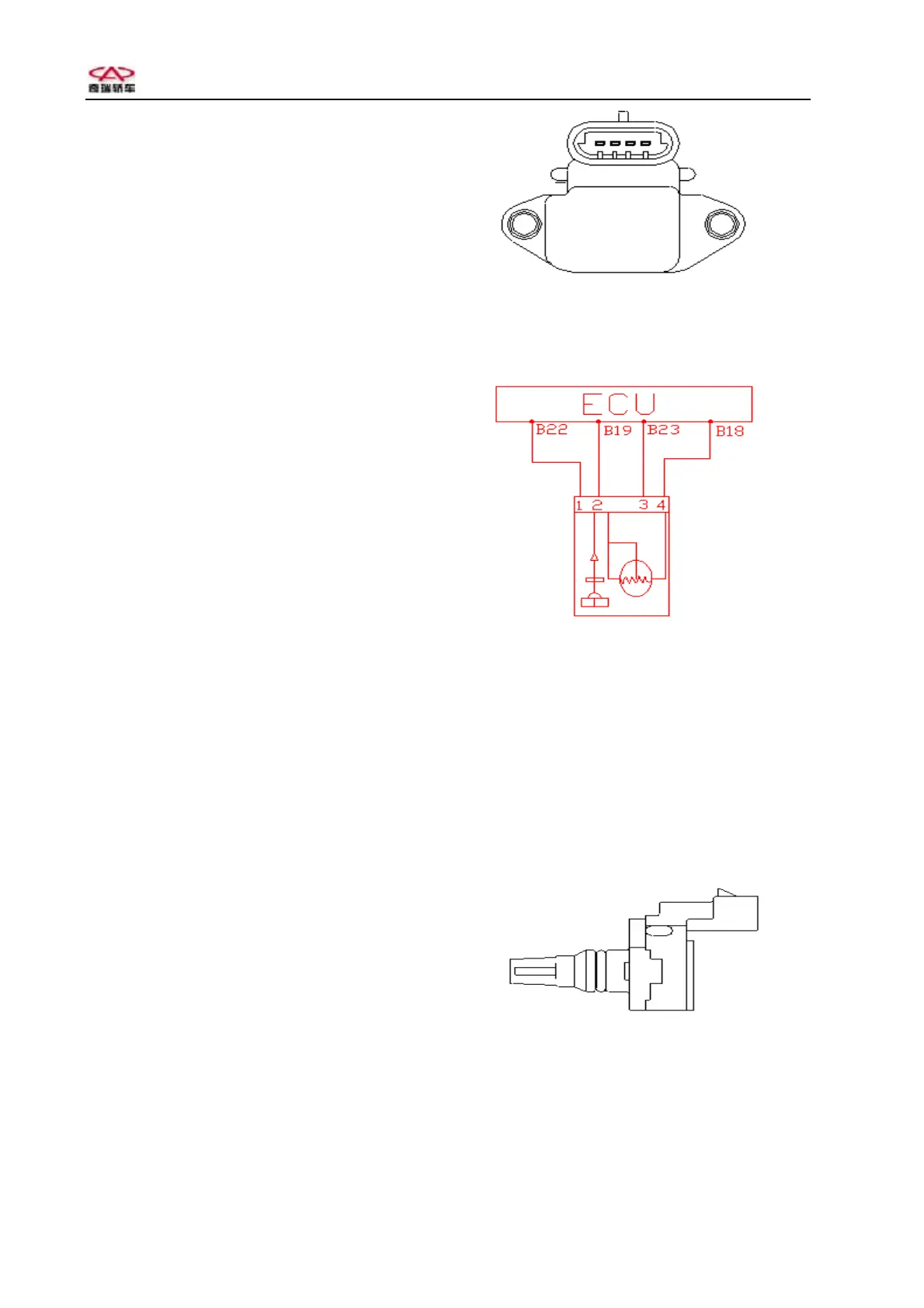
Circuit diagram of manifold absolute pressure and intake
air temperature sensor
Pins: 1# connects with standard 5V power
source (connecting ECU B22#);
2# outputs pressure signal (connecting
ECU B19#);
3# sensor ground (connecting ECU
23#);
4# outputs temperature signal
(connecting ECU B18#).
Side view of intake pressure and intake air temperature
sensor