Maintenance Manual for Chery·Windcloud MOTOROLA EFI System
5
5. Oxygen Sensor
Purpose: this sensor is designed to provide the
information that if there is surplus oxygen after
full combustion of fuel, which is injected into
engine cylinder in the intake air. ECU, when
applying this information, can carry out fuel
quantitative closed-loop control so as to
achieve utmost conversion and purification of
the three major toxic elements (HC, CO and
NOX) in the engine exhaust with the application
of three-way catalytic converter.
Composition and principle: sensing element
of oxygen sensor is a porous ceramic pipe, the
outer side of pipe wall is surrounded by engine
exhaust, while inner side vents to atmosphere.
According to inside and outside oxygen
concentration difference, sensor figures out
indirectly the fuel injection pulse width, and
transfer to ECU, and the ECU controls the
injection again.
The working voltage of oxygen sensor
fluctuates between 0.1-0.9V, 5-8 variations in
10 seconds is required; if lower than such
frequency value, it shows that the sensor is
aged, and needs replacement. The said sensor is
unrepairable.
Failure diagnosis: ECU monitors on various
sensors, actuators, power amplification circuits
and sensing circuits. In case any of the
following situations occurs, failure mark of the
oxygen sensor is set.
Accumulator voltage is unreliable
Manifold absolute pressure signal is unreliable
Engine coolant temperature signal is unreliable.
Injector driver stage failure
After oxygen sensor failure mark is set, fuel
quantification closed-loop control is shut down,
and the primitive fuel injection time stored in
ECU is used to carry out fuel quantification.
Installation hints: the tightening torque of
oxygen sensor is 50-60Nm, a layer of rust
preventive oil shall be applied on oxygen
sensor after replacing so as to prevent from
incapable removal in case of rust.
Troubleshooting: mainly check if the plug
connection of several wires on the sensor is
in good condition, and if there is short circuit
or open circuit.
Generally, sensor damage is caused by
plumbum and phosphorus poisoning, so pay
attention to fuel quality, meanwhile excessive
consumption of engine oil is liable to result
in sensor failure.
The variation frequency of oxygen sensor
shall not be lower than a certain value within
a specified time.
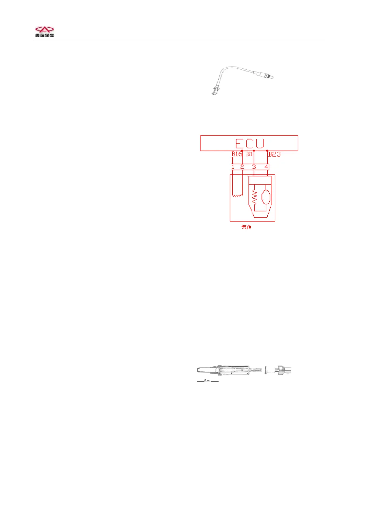
Oxygen sensor
Main
power
Ox
en senso
Circuit diagram of oxygen sensor
Oxygen sensor has a cable, the other end of
which is electric connection. The outside of
sensor is wrapped with asbestos fireproof
covering.
There are 4 pins on the joint:
1# connecting with heating power supply and
main relay;
2# connecting with heating control (ECU B16);
3# connecting with sensor signal anode (ECU
B1#);
4# connecting with sensor signal cathode (ECU
B23#).
Interior structure of oxygen sensor