advanced identification and correction strategy such as enrich air/fuel mixture shall be
adapted to reduce ignition advance angle.
Operational theory: Knock sensor consist of piezoelectric non-resonant quartz and
converts electric signal into mechanical energy in form vibrations. The sensor is
connected to engine ECU through a shielded wire. When knock occurs, ECU will receive
peak values of high-energy signal, which is discriminable from normal combustion signal.
During knocking, air/fuel mixture shall accordingly enrich to ensure exhaust temperature is
within the safe specification when appropriate reducing of ignition advance angle is needed,
The knock sensor is installed on the cylinder body between cylinder2 and cylinder3,
on the side of intake manifold. Tighten torque is 19.6±4.9Nm. USE SPECIAL CARE to
this torque specification.
5. Preventing fuel from evaporating and fuel vapor recycle system
By this system, fuel vapor formed in fuel tank and fuel feed system is combusted in engine
combustion chamber after filtering, prevent fuel vapor from being exhausted into
atmosphere.
(1) Active carbon canister
Active carbon canister is used for absorbing and storing fuel vapor in fuel tank and fuel
vapor is then transferred into air intake manifold through carbon canister control solenoid.
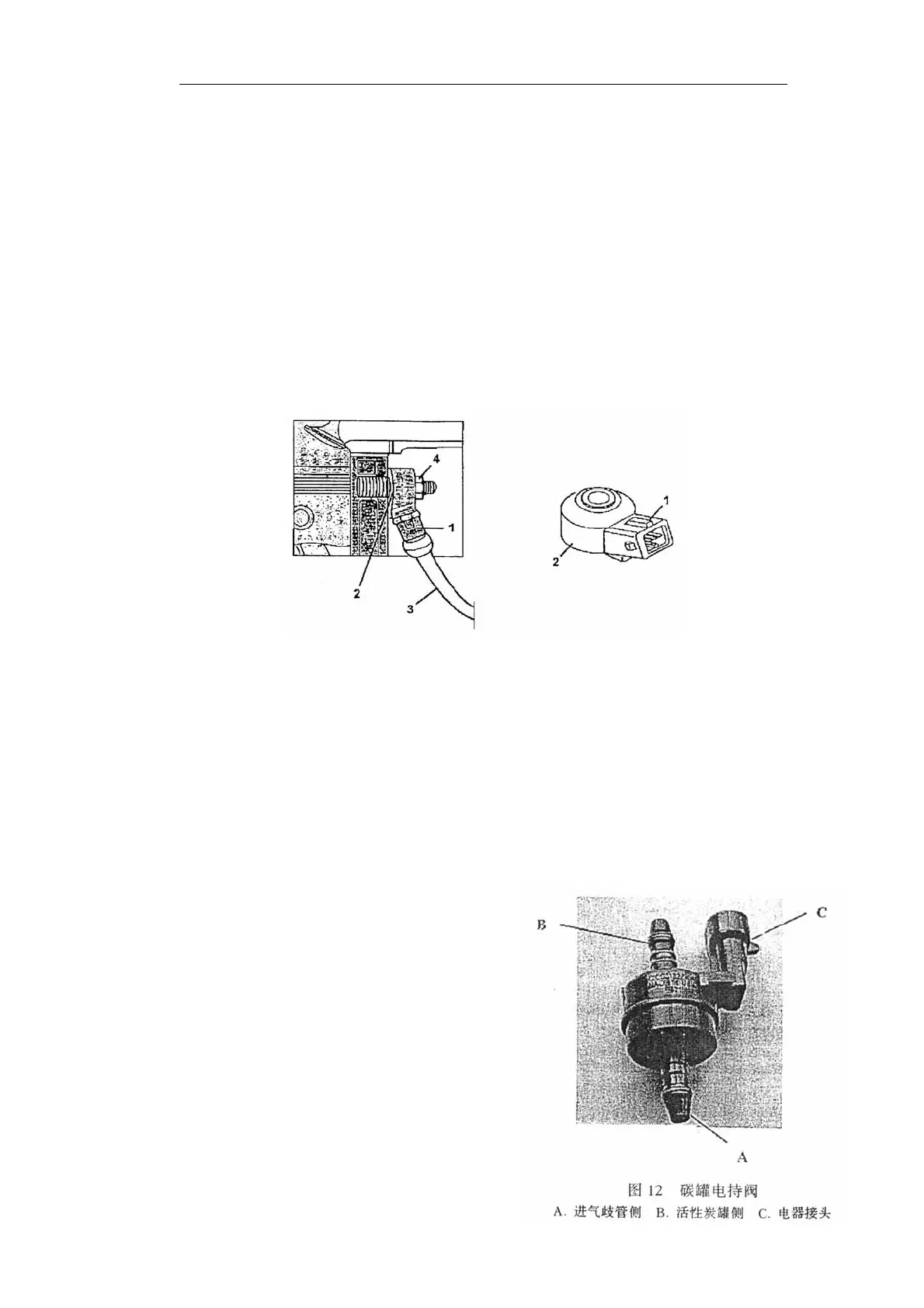
(2) Carbon canister solenoid
Under the control of ECU, carbon canister
solenoid has the following functions:
1. When ngine stop running and under stop
condition, carbon canister solenoid prevent
fuel vapor in fuel tank from entering air intake
manifold. When ignition key is turned to MAR
position, closed carbon canister solenoid will
start to work. l start to work.
2. At the stage of engine start-up, carbon canister
keep closed to prevent fuel vapor over enriching
air/fuel mixture, which will last till engine
Fig 11 Konck Sensor
1. Knock sensor connector 2. Knock sensor 3. Sensor wiring 4. locking nut