Maintenance Manual for Chery·Windcloud M7.9.7 EFI System
4. Knock Sensor KS
Purpose: this sensor is designed to provide
ECU with engine knocking information so
as to carry out knocking control.
Composition and principle: knock sensor
is a sort of vibration acceleration sensor,
which is fixed on engine cylinder block.
ECU controls engine ignition via signals
detected by pressure-sensing element.
Failure diagnosis: ECU monitors on
various sensors, actuators, power
amplification circuits and sensing circuits. In
case any of the following situations occurs,
failure mark of the knock sensor is set.
Knock sensor failure
Knocking control data processing circuit
failure
Cylinder-detecting signal is unreliable
After failure mark of knock sensor being set,
knocking closed-loop control is shut down,
reduceing a safety angle from the ignition
advance angle stored in ECU. When error
frequency cuts down to below setting value,
failure mark restores.
Installation hint: tightening torque is
20±5Nm.
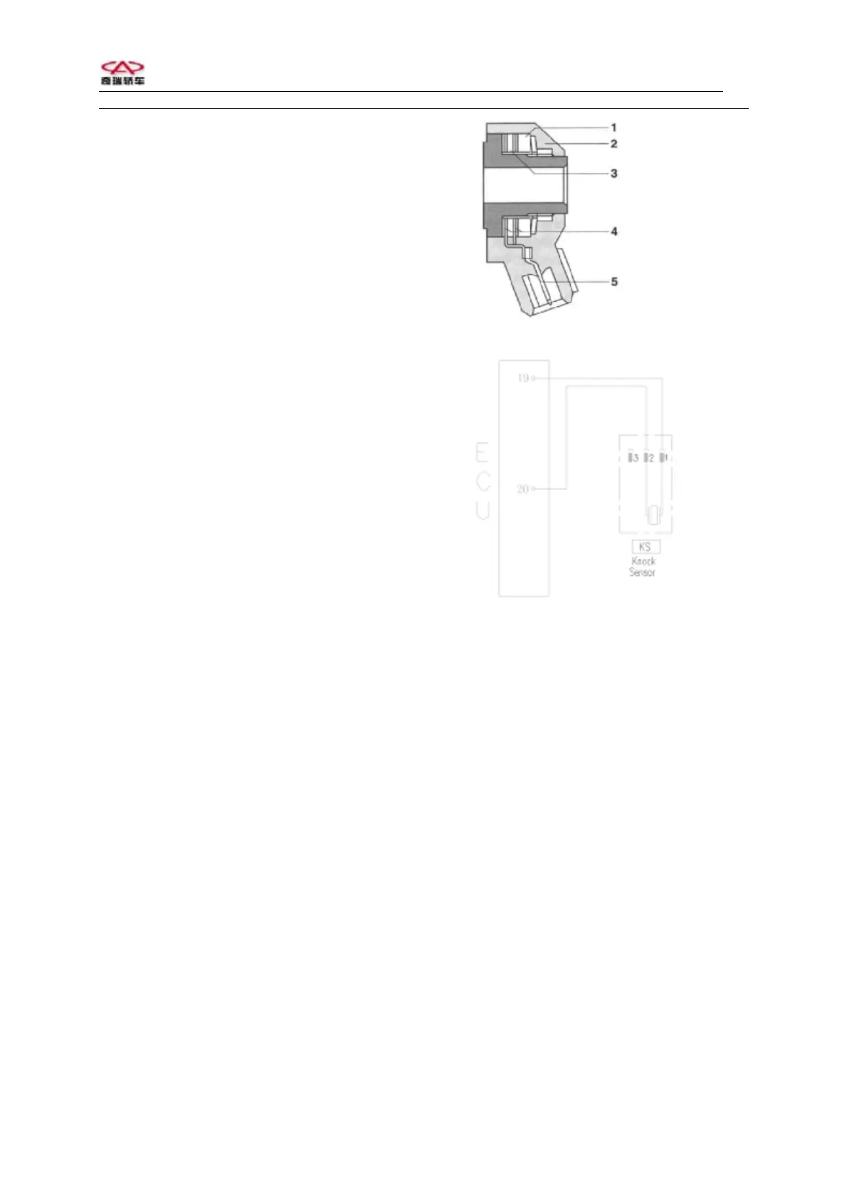
Knock sensor with cable
1.
noc
ing bloc
2. Casing
3. Piezoelectric ceramics
4. Contactor
5. Electric connection
Circuit diagram of knock sensor
Pins:
1 Knock sensor signal 1 (ECU19#)
2 Knock sensor signal 2 (ECU20#)
Troubleshooting: mainly check if there is
short circuit or open circuit on the
connection between 2 lines on senosr and
corresponding ECU pins.
If gasket is added during installation; if
tightening torque is proper.
If there is stitching defect between sensor
and cylinder, or there is foreign matter
between them.
4