[DB600] General instruction manual
- 143 -
□□□ □:
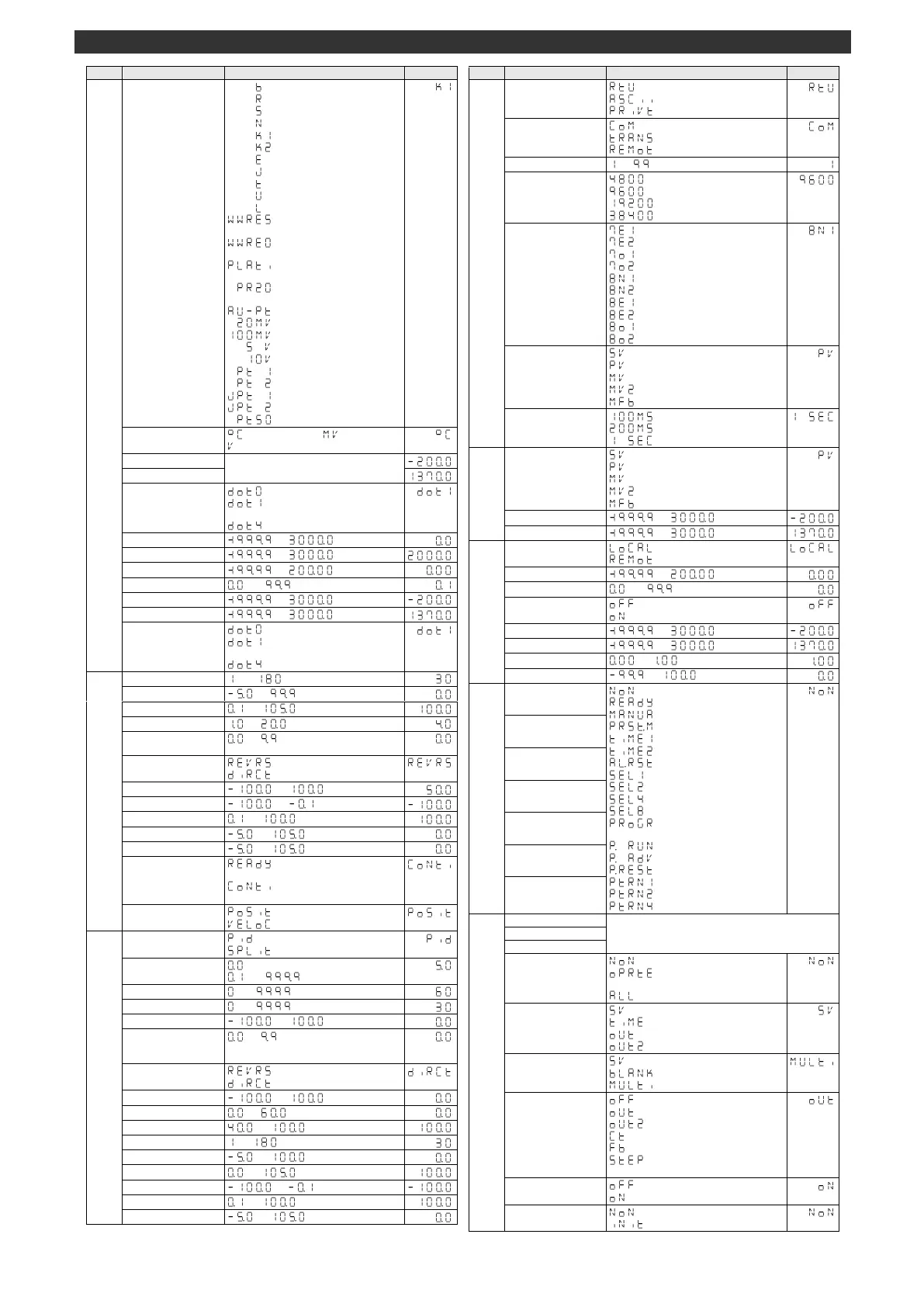
Thermocouple B (0.0 to 1820.0°C)
□□□ □:
Thermocouple R (0.0 to 1760.0°C)
□□□ □:
Thermocouple S (0.0 to 1760.0°C)
□□□ □:
Thermocouple N (0.0 to 1300.0°C)
□□□
: Thermocouple K1 (-200.0 to 1370.0°C)
□□□ :
Thermocouple K2 (-200.0 to 500.0°C)
□□□ □:
Thermocouple E (-200.0 to 900.0°C)
□□□ □:
Thermocouple J (-200.0 to 1200.0°C)
□□□ □:
Thermocouple T (-200.0 to 400.0°C)
□□□ □:
Thermocouple U (-200.0 to 400.0°C)
□□□ □:
Thermocouple L (-200.0 to 900.0°C)
:
Thermocouple W-WRe5-26
(0.0 to 2310.0°C)
:
Thermocouple W-WRe26
(0.0 to 2310.0°C)
:
Thermocouple PlatinelII
(0.0 to 1390.0°C)
□ :
Thermocouple PtRh40-20
(0.0 to 1880.0°C)
:
Thermocouple Au-Pt (0.0 to 1000.0°C)
□
: ±20mV (-20.00 to 20.00mV)
: ±100mV (-100.0 to 100.0mV)
□□ □
: ±5V (-5.000 to 5.000V)
□□
: ±10V (-10.000 to 10.000V)
□ □
:
Pt 100_1 (-200.0 to 850.0°C)
□ □
:
Pt 100_2 (-200.0 to 200.0°C)
□
:
JPt 100_1 (-200.0 to 649.0°C)
□
:
JPt 100_2 (-200.0 to 200.0°C)
□
:
Pt 50 (-200.0 to 649.0°C)
Within the range (* See input type)
: No decimal point
: 1 digit after decimal point
□□to
: 4 digits after decimal point
: No decimal point
: 1 digit after decimal point
□□to
: 4 digits after decimal point
PID dead band/
output dead band
: Heating control
: Cooling control
Output variation limiter L
Output variation limiter H
: READY status/program
operation RESET
: Operation right before
previous power-OFF
: Position PID control
: Velocity PID control
□□: PID control
: Split control
: Two-position control
to [%]
Output 2
PID dead band/
output dead band
: Heating control
: Cooling control
Output 2 output limiter L
Output 2 output limiter H
Output 2 variation limiter L
Output 2 variation limiter H
□□:MODBUS RTU
:MODBUS ASCII
:Private
□□: Host communication
: Digital transmission
: Digital remote input
Communication
transmission rate
□:4800bps
□:9600bps
:19200bps
:38400bps
: 7-bit/even parity/stop bit 1
: 7-bit/even parity/stop bit 2
: 7-bit/odd parity/stop bit 1
: 7-bit/odd parity/stop bit 2
: 8-bit/no parity/stop bit 1
: 8-bit/no parity/stop bit 2
: 8-bit/even parity/stop bit 1
: 8-bit/even parity/stop bit 2
: 8-bit/odd parity/stop bit 1
: 8-bit/odd parity/stop bit 2
Digital transmission
type
□: Digital SV transmission
□: Digital PV transmission
□: Digital output 1 transmission
: Digital output 2 transmission
: Digital FB transmission
Digital transmission
interval
: 100msec interval
: 200msec interval
□ : 100msec interval
□: SV transmission signal output
□: PV transmission signal output
□: Output 1 transmission signal output
: Output 2 transmission signal output
: FB transmission signal output
: Local SV operation
: Remote SV operation
Tracking at
switch to local
: Function OFF
□: Tracking ON
□□: Function OFF
: RUN/READY switch
: AUTO/MANUAL switch
: Preset manual
: Timer 1
: Timer 2
: Alarm event reset
□: Execution No. selection 1 (Bit0)
□: Execution No. selection 2 (Bit1)
□: Execution No. selection 4 (Bit2)
□: Execution No. selection 8 (Bit3)
: Program/constant value
operation switch
□ :
Program operation RUN/STOP
□ : Program operation ADVANCE
: Program operation RESET
: Program pattern 1 (Bit0)
: Program pattern 2 (Bit1)
: Program pattern 4 (Bit2)
Model No. (1) (2) (3) (4) (5)
Model No. (6) (7) (8) (9) (10)
Model No. (11) (12) (13) (14)
□□: No key lock
: Operation parameter keys
locked
□□: All parameter keys locked
□□: PV/SV display screen
: PV/step time display screen
□: PV/output 1 display screen
: PV/output 2 display screen
Operation screen SV
display
□□□: SV display
: Blank display
: Multi display
□□: No display
□□: Output 1 value display
□: Output 2 value display
□□□: CT measured value display
□□□: FB measured value display
□: Step remaining/elapsed time
display
: Backup function OFF
□:Backup function ON
□: No initialization
: Initialization executed
 Loading...