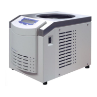
Freeze-dryer Alpha 1-4 LSCplus
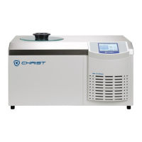
Freeze-dryer Alpha 2-4 LSCplus
Version 01/2011, Rev. 2.3 of 03/07/2017 • sb
Translation of the original operating manual
5.2 Power supply
5.2.1 Connection
The operating voltage on the name plate must correspond to the local
supply voltage
CHRIST freeze-dryers are units of safety class I.
Alpha 1-4 LSCplus and Alpha 2-4 LSCplus units have a three-wire
power cord with a fixed cable(see chapter 10 - "Technical data").
An equipotential bonding screw is located on the back below the mains
power input (see chapter 2.1.1 - "Functional and operating elements"). This
equipotential bonding screw can be used to perform an earth conductor
check.
5.2.2 Customer-provided fuses
Typically, the freeze-dryer must be protected with 16 Amp G fuses that are
to be provided by the customer.
5.3 Aeration valve
The aeration valve is located on top of the left side of the unit (see chapter
2.1.1 - "Functional and operating elements").
After the end of a freeze-drying process, the unit will be aerated via the
aeration valve.
The ice condenser chamber can be flooded with nitrogen via the hose
nozzle of the aeration valve.
5.4 Media drain valve
The media drain valve is located at the bottom of the left side of the unit
(see chapter 2.1.1 - "Functional and operating elements"). It is used to
drain off the condensate and the defrosting water.
• Connect the drain hose (included in the scope of supply) to the hose
connector.
• Place a collecting vessel under the unit.
The hose must be laid with a continuous slope and the end of the hose
must always be above the liquid level in the collecting vessel. This prevents
water and dirt residues from being sucked into the ice condenser chamber
if there is negative pressure when the media drain valve is opened.