27
Appendix
Below is the parameter settings chart organized by Menu Screen. It includes the default, minimum, maximum
and / or the range of settings, where applicable.
Parameter Default Min Max
Temperature Setpoint 0˚F (-18˚C) -80˚F (-62˚C) 1100˚F (-593˚)
Hi Temp Setpoint 200˚F (-93˚C) -80˚F (-62˚C) 1100˚F (-593˚)
Lo Temp Setpoint 33˚F (-1˚C) -80˚F (-62˚C) 1100˚F (-593˚)
HI Current 50 Amp 0.2 Amp 50 Amp
Lo Current 0.2 Amp 0 Amp 50 Amp
GFEP 30 mA 20 mA 150 mA
Control Mode Manual Manual Auto
Output % 0 0 100
PID or ON/OFF On/OFF PID On/OFF
Deadband 10 2 100
Proportional Band (%) 20 1 100
Integral 8 0 100
Derivative 2 0 500
Soft Start Enabled Enabled Disabled
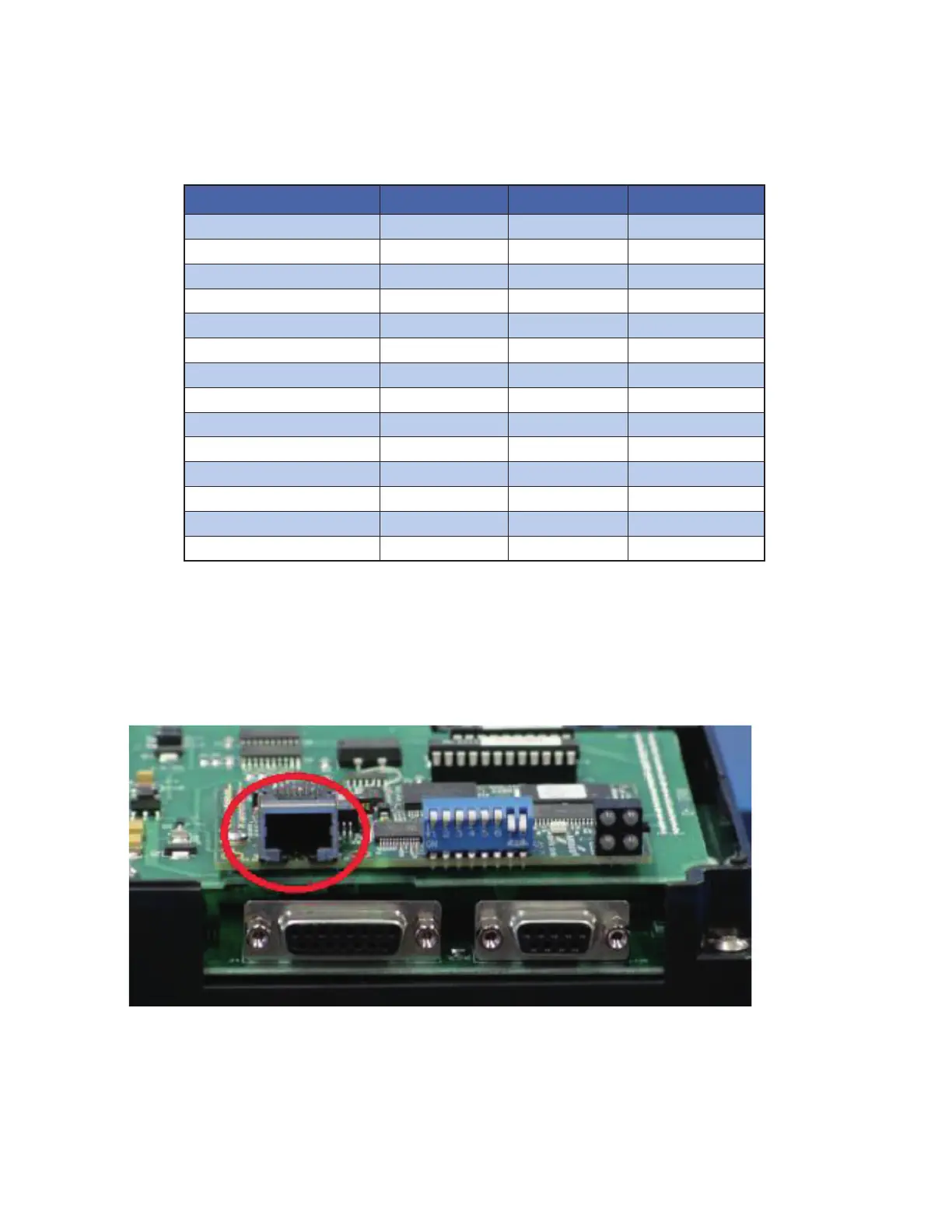
Wiring Considerations
• The maximum distance between ITLS panel and router can be 100m. If this distance needs to be ex-
tended it would be necessary to utilize an inline repeater.
• Cable that should be used is CAT5 RJ45 Ethernet cable.
• The HMI display has 1 Ethernet port on the back of the display (see photo below).
• Insert one end of the Ethernet cable into the HMI and the other end into customer’s network hub or
router. All HMI’s must be connected the same way.
• Typically the IP address of each HMI is assigned automatically by the DHCP Host.
• Every HMI Touch Screen Computer must have different Modbus (Slave) ID and a different IP address.
These are found on the ITLS or ITAS COMMs page.
• In order to communicate all HMI’s and the ISC Supervisory Control system must be in the same net-
work.
 Loading...


