WELDSKILL 100, 135, 150 MIG
4-1
Operation
SECTION 4:
OPERATION
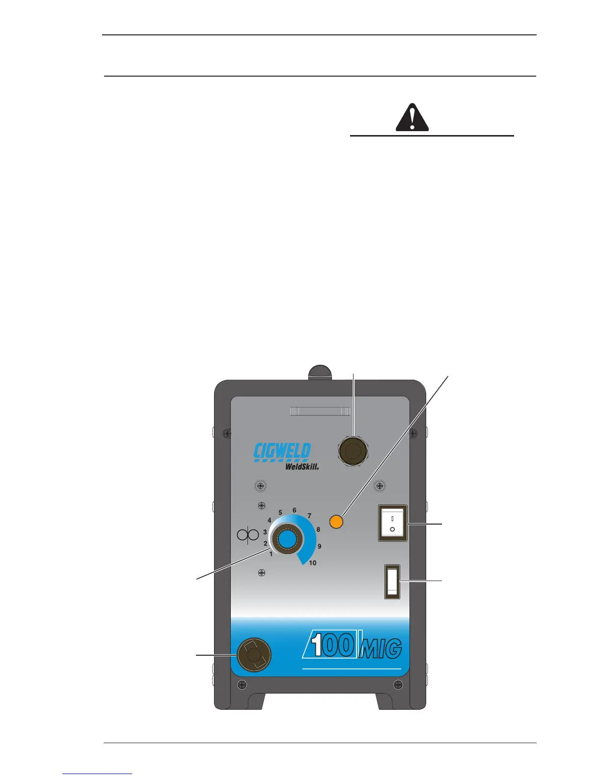
4.01 WeldSkill 100 Mig Power Source Controls, Indicators and Features
A. MIG Gun Cable End Port
The MIG Torch cable and MIG Torch switch leads
are routed through this opening.
B. Over Heat Indicator
The Power Source is protected by a self resetting
thermostat. The Indicator will illuminate and weld-
ing current ceases if the duty cycle of the power
source has been exceeded. If the Over Heat Indica-
tor Illuminates wait for the Over Heat Indicator to
extinguish before resuming welding.
C. Control On/Off Switch with in-built Indicator Light
The Control On/Off Switch Indicator illuminates
when the Control On/Off switch is in the On position
and the correct mains voltage is present.
D. Output Voltage Control Switch
The Output Voltage Control Switch sets the voltage
range of the welding output.
CAUTION
The Output Voltage Control Switch MUST
NOT BE SWITCHED during the welding
process. Some internal electrical compo
-
nents are at Mains voltage potential with
this switch in the OFF position.
E. Work Cable and Clamp Port
The work cable and clamp are routed through this
opening.
F. Wirespeed Control
The Wirespeed Control knob controls the weld-
ing current via the electrode wire feed rate which
determines the speed of the wire feed motor.
OVERHEAT
CONTROL
ON
OFF
WIRESPEED
OUTPUT
VOLTAGE
Do not switch
while welding
HIGH
LOW
00
Gasless Welding Machine
MIG
B
A
C
F
D
E
Art # A-09018_AB
Figure 4-1: Weldskill 100 Mig Front Panel