WELDSKILL 100, 135, 150 MIG
4-3
Operation
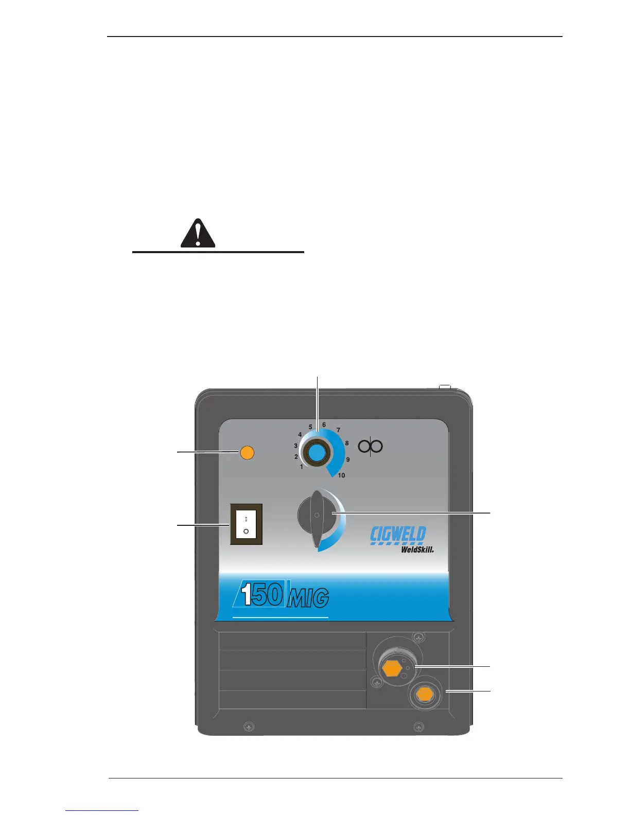
4.03 WeldSkill 150 Mig Power Source Controls, Indicators and Features
A. Wirespeed Control
The Wirespeed Control knob controls the weld-
ing current via the electrode wire feed rate which
determines the speed of the wire feed motor.
B. Output Voltage Control Switch
The Output Voltage Control Switch sets the volt-
age level to the welding terminals as it is rotated
in the clockwise direction. There are 4 positions
available. The OFF switch position disconnects the
power from the controls.
CAUTION
The Output Voltage Control Switch MUST
NOT BE SWITCHED during the welding
process. Some internal electrical compo
-
nents are at Mains voltage potential with
this switch in the OFF position.
C. MIG Torch Connection (Euro)
Fit the MIG Torch to the Power Source by pushing
the torch connector into the torch adaptor and
screwing the plastic torch nut clockwise to secure
the torch to the torch adaptor.
D. Work Cable and Clamp Port Dinse Connector Socket
The work cable and clamp are routed through this
opening.
E. Control On/Off Switch with in-built Indicator Light
The Control On/Off Switch Indicator illuminates
when the Control On/Off switch is in the On position
and the correct mains voltage is present.
F. Over Heat Indicator
The Power Source is protected by a self resetting
thermostat. The Indicator will illuminate and weld-
ing current ceases if the duty cycle of the power
source has been exceeded. If the Over Heat Indica-
tor Illuminates wait for the Over Heat Indicator to
extinguish before resuming welding.