5° to 15°
Longitudinal
Angle
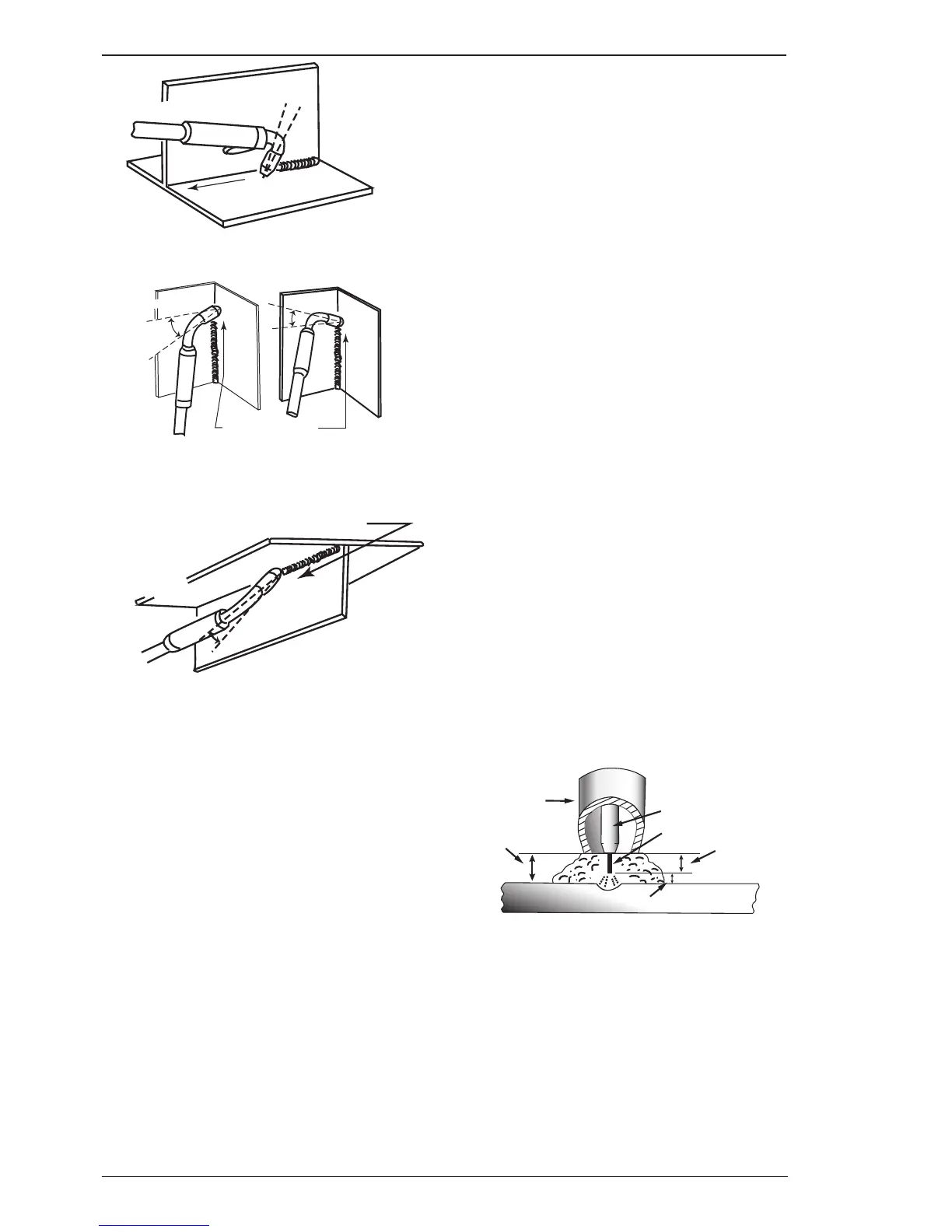
Figure 4-11
Distance from the MIG Torch Nozzle to the Work
Piece
The electrode wire stick out from the MIG Torch nozzle
should be between 10mm to 20.0mm. This distance
may vary depending on the type of joint that is being
welded.
Travel Speed
The speed at which the molten pool travels influences
the width of the weld and penetration of the welding
run.
MIG Welding (GMAW) Varialbes
Most of the welding done by all processes is on
carbon steel. The items below describe the welding
variables in short-arc welding of 24gauge (0.024”,
0.6mm) to ¼” (6.4mm) mild sheet or plate. The ap-
plied techniques and end results in the GMAW process
are controlled by these variables.
Preselected Variables
Preselected variables depend upon the type of material
being welded, the thickness of the material, the weld-
ing position, the deposition rate and the mechanical
properties. These variables are:
1. Type of electrode wire
2. Size of electrode wire
3. Type of gas (not applicable to self shielding
wires FCAW)
4. Gas flow rate (not applicable to self shielding
wires FCAW)
Primary Adjustable Variables
These control the process after preselected variables
have been found. They control the penetration, bead
width, bead height, arc stability, deposition rate and
weld soundness. They are:
1. Arc Voltage
2. Welding current (wire feed speed)
3. Travel speed
Secondary Adjustable Variables
These variables cause changes in primary adjustable
variables which in turn cause the desired change in
the bead formation. They are:
1. Stick-out (distance between the end of the
contact tube (tip) and the end of the electrode
wire). Maintain at about 10mm stick-out
2. Wire Feed Speed. Increase in wire feed speed
increases weld current, Decrease in wire feed
speed decreases weld current.