Testpoint
No.
Inrush Resistor Multimeter Lead Placement
Ohms (Ω)
Acceptable Results
11
12
PTC Resistor
MZ71
18RM270
Negative (black) meter lead to testpoint 11
Positive (red) meter lead to testpoint 12
36+/-20% Ω
Table 10-4 Inrush PTC, Multimeter set to measure ohms (Ω)
Testpoint
No.
DIODE
Testing
Multimeter Lead Placement Testing
Diode Voltage VDC
Acceptable Results
13
14
DIODE D5 Negative (black) meter lead to testpoint 13
Positive (red) meter lead to testpoint 14
D5
anode-cathode
0.2 – 0.8 VDC
15
16
DIODE D4 Negative (black) meter lead to testpoint 15
Positive (red) meter lead to testpoint 16
D4
anode-cathode
0.2 – 0.8 VDC
17
18
DIODE D14 Negative (black) meter lead to testpoint 17
Positive (red) meter lead to testpoint 18
D14
anode-cathode
0.2 – 0.8 VDC
19
20
DIODE D2 Negative (black) meter lead to testpoint 19
Positive (red) meter lead to testpoint 20
D2
anode-cathode
0.2 – 0.8 VDC
21
22
DIODE D1 Negative (black) meter lead to testpoint 21
Positive (red) meter lead to testpoint 22
D1
anode-cathode
0.2 – 0.8 VDC
Table 10-5 Diodes, Multimeter set to measure Diode Voltage
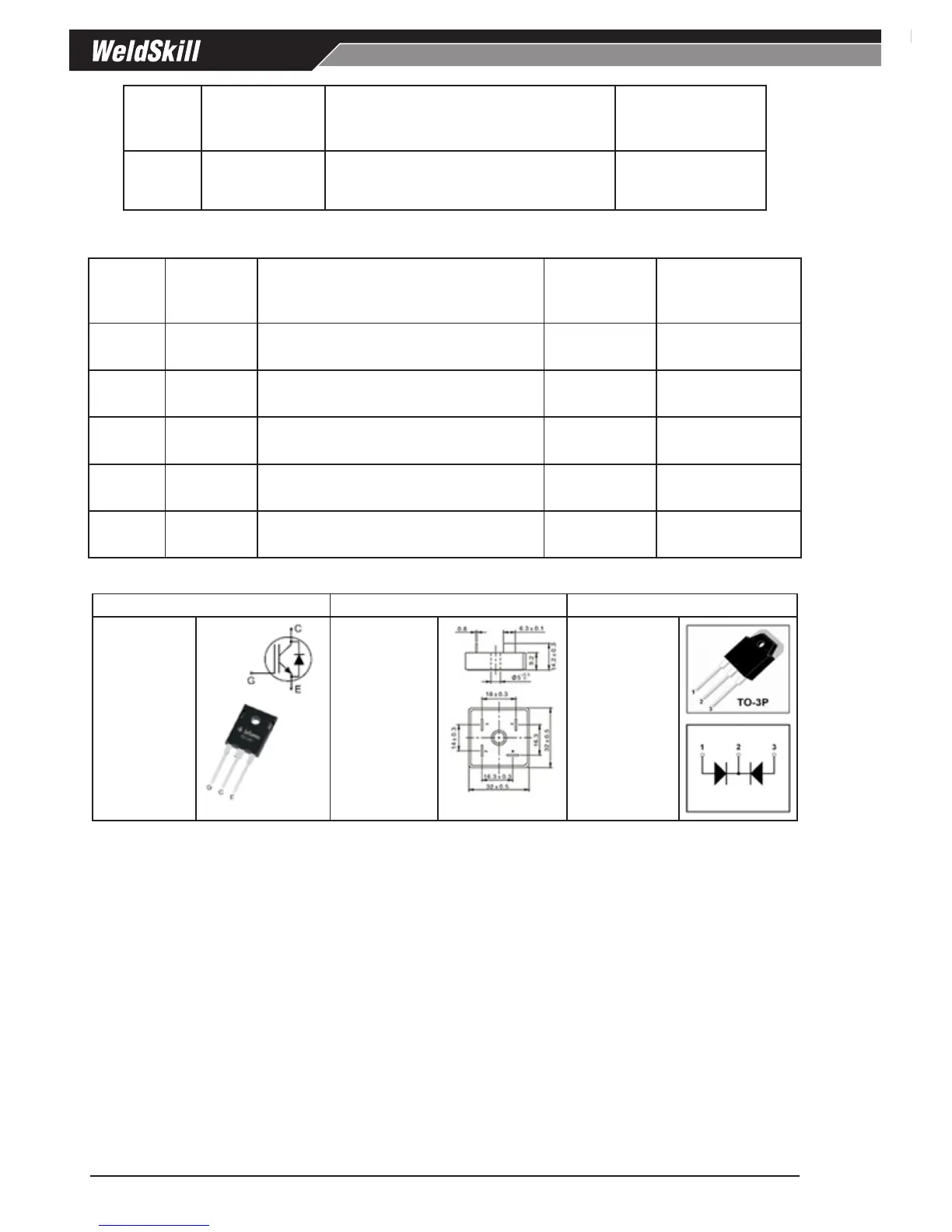
IGBT Q4, Q1, Q3, Q2 Bridge Rectifier B1 DIODE D5, D4, D14, D2, D1
Type:
IKW50N65H5
Vce: 650V
Ic: 50A
Type:
BR6010-7
Vr: 1000V
If: 60A
Type:
MM60F060PC
Vr: 600V
If: 60A per
package
Table 10-6 Primary Bridge Rectifier / IGBT / Secondary Diode specifications
 Loading...


