AC4
P2
P1
P5
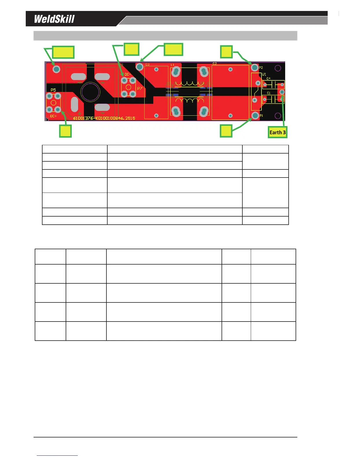
Power Terminal Name Terminal function Signal
P1 Neutral 240 VAC connection into EMC filter
240 VAC Between
Terminal P1 & P2
P2
Active 240 VAC connection into EMC filter
EARTH 3
Mains Earth connection to EMC PCB 0 VAC
AC4
Active 240 VAC out of EMC filter to P1 (pre-charge
start circuit) in the inverter PCB
240 VAC Between
Terminal AC4 / P1
and AC4-1 / P1
AC4-1
Active 240 VAC into the bridge rectifier from the
inverter PCB pre-charge start circuit
P5
DC+ voltage out of the bridge rectifier 340VDC
P7
DC- voltage out of the bridge rectifier 0VDC
Table 12-8 Power Terminal function (connects to EMC PCB)
Input Bridge Rectifier Check in EMC PCB
Testpoint
No.
Input Rectifier
Testing
Multimeter Lead Placement Testing Diode Voltage
P5
P1
DC+ to
~ (AC)
Negative (black) meter lead to P5
Positive (red) meter lead to testpoint P1
cathode
-anode
0.2 – 0.8 VDC
P5
AC4-1
DC+ to
~ (AC)
Negative (black) meter lead to P5
Positive (red) meter lead to testpoint AC4-1
cathode
-anode
0.2 – 0.8 VDC
P7
P1
DC- to
~ (AC)
Positive (red) meter lead to testpoint P7
Negative (black) meter lead to testpoint P1
anode
-cathode
0.2 – 0.8 VDC
P7
AC4-1
DC- to
~ (AC)
Positive (red) meter lead to testpoint P7
Negative (black) meter lead to testpoint AC4-1
anode
-cathode
0.2 – 0.8 VDC
Table 12-9 Input Rectifier, Multimeter set to measure Diode Voltage