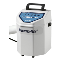
WarmAir
Model 135 Manual REPAIR PROCEDURES
Page 31 of 43
Repair Procedures
The repair procedures contained herein allow qualified Medical Equipment persons to repair the
WarmAir
135 unit. Service training is available for this WarmAir
135 unit and other CSZ
equipment. For further information, contact CSZ Medical Technical Service Department.
The WarmAir
135 unit must be turned OFF and the power cord must be unplugged before replacing
any parts. The WarmAir
135 unit is isolated from the mains power supply by unplugging the power
cord at the WarmAir
135 unit or at the outlet.
The exploded views of the WarmAir
135 unit below can be used to replace parts. Replacement parts
should be installed in the reverse order of removal unless instructions specify otherwise.
When installing the electrical components below, follow the accompanying
instructions. Failure to follow instructions could result in electric
shock.
Replacing the Hose
1. Request CSZ repair part.
2. Unplug the unit.
3. Remove the top exterior cover and thermistor.
4. Unscrew (left hand threads) the hose from the blower housing.
5. Secure new hose.
6. Use an Exacto knife or equivalent to create an “X” cut in the hose through the thermistor
hole.
7. Replace the thermistor and top exterior cover.
Replacing the Circuit Breaker Power Switch
1. Request CSZ repair part.
2. Unplug the unit.
3. Remove exterior top cover and exterior wrap (optional).
4. Squeeze the snap tabs on the sides of the switch to allow the switch to slide out of the cutout in
the cabinet.
5. Unfasten the four slide-on connectors from the power switch.
6. Secure the Faston connectors to the new switch, ensuring proper orientation of switch.
7. Push the power switch back into the cabinet until it snaps into place.
8. Perform all leakage current and grounding integrity tests.