22
CVM-C4
Instruction Manual
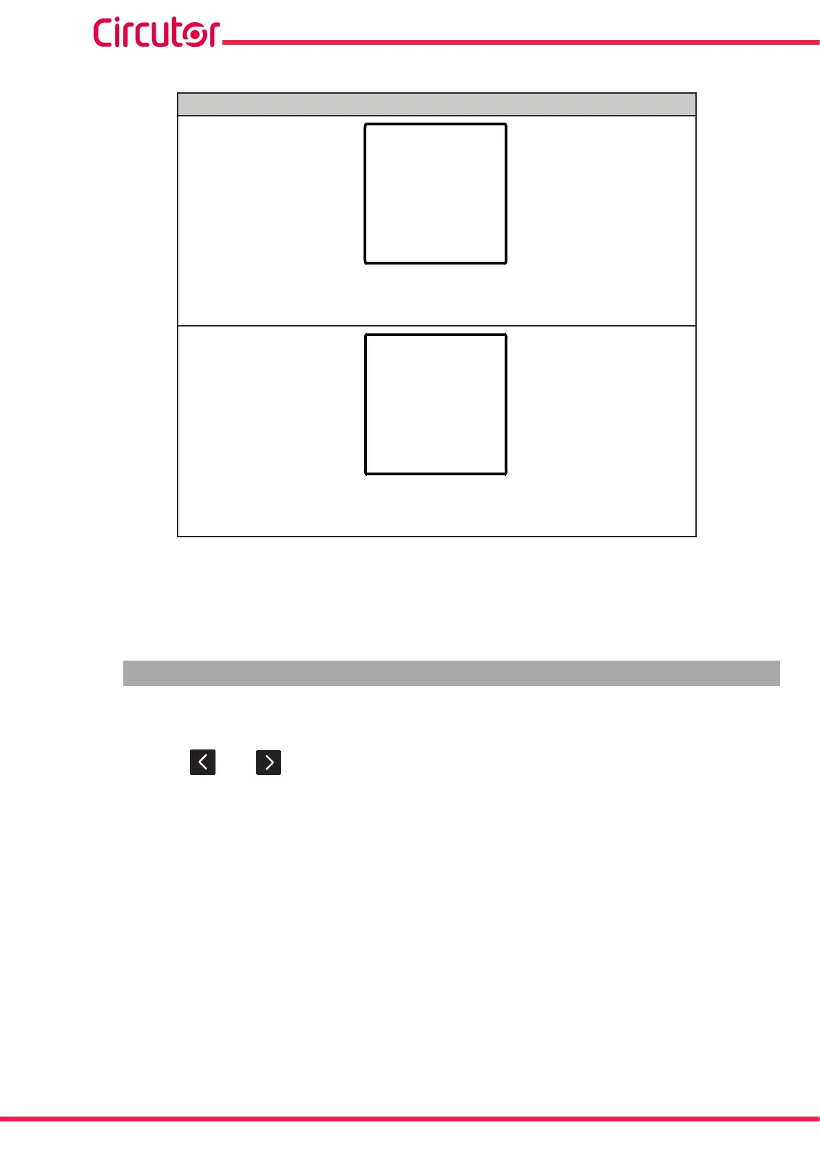
Table 9 (Continued). Display menu: Single-phase network measuring
Display menu: Single-phase network measuring
di
12
Status of digital inputs
1, status of digital input 1: flashes when the input has been activated.
2, status of digital input 2: flashes when the input has been activated.
do
12
Status of relay outputs
1, status of relay output 1: flashes when the relay has been activated.
2, status of relay output 2: flashes when the relay has been activated.
If the input voltage or current value higher than a % of the nominal value, the device can make the
digits on the display start flashing, in the form of a light alarm. See “6.5.6.- LIGHT ALARM”
Note: If a display screen shows FFFF, check the programming of the transformation ratios.
5.2.- THREE-PHASE NETWORK MEASURING WITH 4-WIRE CONNECTION
The CVM-C4 has 24 display screens in the three-phase network measurement system with a 4-wire
connection, Table 10.
Use the keys and to browse through the different screens.
The display screens can change automatically depending on the time programmed in the section
“6.5.2.- CYCLIC DISPLAY”.
The initial display screen, i.e. the first screen displayed when feeding the device or when exiting the
configuration menu, can be programmed in section “6.5.4.- INITIAL DISPLAY SCREEN”.