Home
Circutor
Battery Charger
Raption Series
Circutor Raption Series Service Manual
5
of 1
of 1 rating
112 pages
Give review
Manual
Specs
To Next Page
To Next Page
To Previous Page
To Previous Page
Loading...
Raption
42
Ser
vice Manual
Electrical scheme
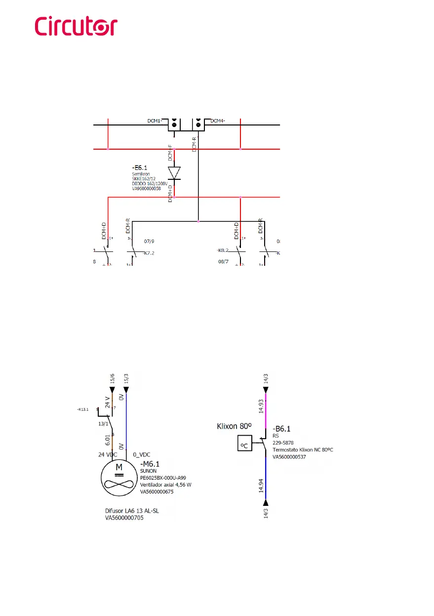
Backflow diode is located just after the power modules,
when positive and negative wire
are collected,
and before the output contactors.
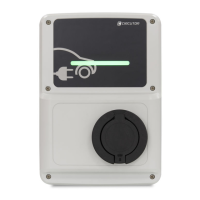
And in the next picture:
•
Fan,
managed by the Expansion board
•
Clixon system,
that sends an alarm to the Main board if ther
e is a temperatur
e err
or
.
41
43
Table of Contents
Disclaimer
2
Revision Log
2
Table of Contents
4
Contents
4
So, Hello
7
Features
8
Main Features
8
Dimensions
10
Components Overview
11
Control Devices
26
PC Screen (HMI)
26
Mode 4 Board
29
CCS Board
32
Mode 3 Device
34
Disconnector
36
Protection Devices
37
Rcd
37
Mcbs
38
Rcbos
40
Backflow Diode and Clixon
41
Transient Surge Protector
43
Isolation Protection Device
44
Other Components
49
Heater System
49
Ventilation System
51
RFID Reader
52
AC Meter
53
DC Meter
54
Extra Power Supply
55
Power Supplies
56
Contactors
57
Teltonika RUT 240
59
RFID Reader - Legic
60
Other Optional Components
61
Shutter Protection
62
Troubleshooting Introduction
64
Troubleshooting & Errors
65
Log Files
68
Decoding the Error
70
Error Code in Remote
78
Communication Errors
80
OCPP Errors
81
Power Modules Errors
87
Maintenance
91
Annexes
95
Technical Data
97
Raption 50
99
Raption 50 HV / Raption 50 EVO / Raption 100
102
Need Help
111
Guarantee
111
Other manuals for Circutor Raption Series
Instruction Manual
134 pages
5
Based on 1 rating
Ask a question
Give review
Questions and Answers:
Need help?
Do you have a question about the Circutor Raption Series and is the answer not in the manual?
Ask a question
Circutor Raption Series Specifications
General
Brand
Circutor
Model
Raption Series
Category
Battery Charger
Language
English
Related product manuals
Circutor URBAN
68 pages
Circutor WB-eBasic T2S32
2 pages