Rear Panel
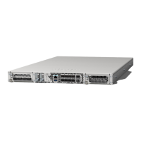
The following figure shows the rear panel of the Secure Firewall 4200.
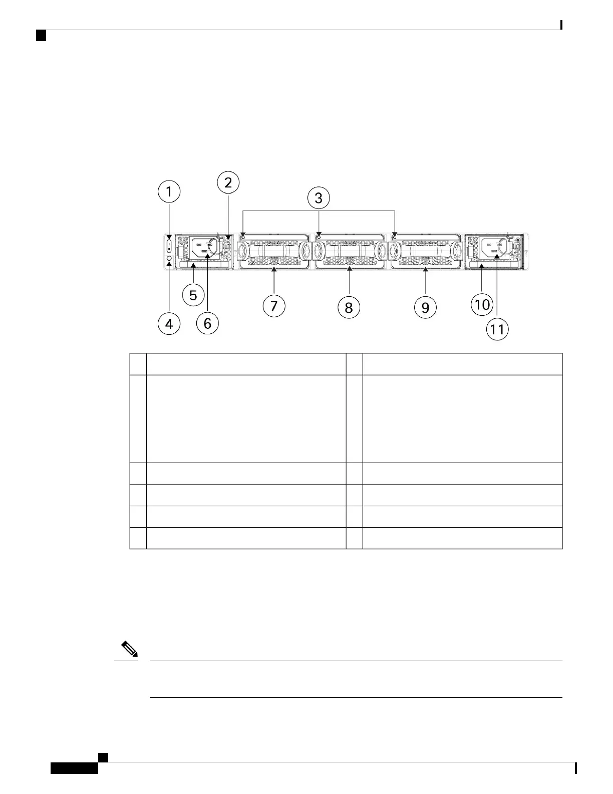
Figure 7: Secure Firewall 4200 Rear Panel
Power supply LED (PSU-1)2Power on/off switch1
System power LED
This system power LED has the same behavior
as the front panel LED. See Front Panel LEDs,
on page 11 for more information.
Power supply module 1 (PSU-1)
Note
4Dual fan modules (FAN-1, FAN-2, FAN-3) LEDs3
Power supply module 1 (PSU-1) connector6Power supply module 1 (PSU-1)5
Dual fan module 2 (FAN-2)8Dual fan module 1 (FAN-1)7
Power supply module 2 (PSU-2)10Dual fan module 3 (FAN-3)9
—Power supply module 2 (PSU-2) connector11
Power Switch
The power switch is located to the left of PSU-1 on the rear of the chassis. It is a toggle switch that
controls power to the system. Turning the switch to OFF starts the graceful shutdown process. During
the shutdown process the power LEDs flash green indicating that the process has started. Once the
shutdown is complete, the system is powered off. Wait for the system power LEDs to turn off before
unplugging the AC power cables. See Front Panel LEDs, on page 11 for the power status LED description.
Threat defense requires a graceful shutdown. See the Cisco Secure 4200 Getting Started Guide for the
procedure.
Note
Cisco Secure Firewall 4200 Series Hardware Installation Guide
14
Overview
Rear Panel
 Loading...