Captive screw6Ethernet 2/7 and 2/8 or Ethernet 3/7 and 3/8
Ports 7 and 8 are paired together to form a
hardware bypass pair. LED B4 applies to this
paired port.
5
Handle8Power LED7
Right Port LED
• Unlit—No connection or port is not in use.
• Green—Link up.
• Green, flashing—Network activity.
10Left Port LED
• Unlit—No connection or port is not in use.
• Green—Link up.
• Green, flashing—Network activity.
9
For More Information
• See 6-Port 10-Gb SR/10-Gb LR/25-Gb SR/25-Gb LR Network Module with Hardware Bypass , on
page 24 for a description of the 1/10/25-Gb network module.
• See 4-Port 40-Gb Network Module, on page 17 for a description of the 40-Gb network module.
• See 8-Port 1/10/25-Gb Network Module, on page 15 for a description of the 1/10/25-Gb network
module.
• See Install, Remove, and Replace the Network Module, on page 63 for the procedure for removing
and replacing network modules.
6-Port 10-Gb SR/10-Gb LR/25-Gb SR/25-Gb LR Network Module
with Hardware Bypass
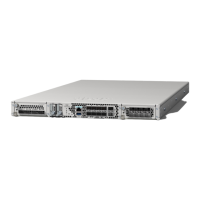
The Secure Firewall 4200 chassis has two network module slots named NM-2 and NM-3 (left to right on the
front panel). Network modules are optional, removable I/O modules that provide either additional ports or
different interface types. The network module plugs into the chassis on the front panel. See Front Panel, on
page 8 for the location of the network module slots on the chassis.
The FPR-X-NM-6X10SRF, FPR-X-NM-6X10LRF, FPR-X-NM-6X25SRF, and FPR-X-NM-6X25LRF
hardware bypass network modules have six ports that are numbered from top to bottom, left to right. Pair
ports 1 and 2, 3 and 4, and 5 and 6 to form hardware bypass paired sets. In hardware bypass mode, data is not
processed by the Secure Firewall 4200 but is routed to the paired port. This network module has built-in SPF
transceivers. Hot swapping and field replacement of transceivers are not supported.
Hardware bypass (also known as fail-to-wire) is a physical layer (Layer 1) bypass that allows paired interfaces
to go into bypass mode so that the hardware forwards packets between these port pairs without software
intervention. Hardware bypass provides network connectivity when there are software or hardware failures.
Hardware bypass is useful on ports where the secure firewall is only monitoring or logging traffic. The
hardware bypass network modules have a switch that is capable of connecting the two ports when needed.
This hardware bypass network module has built-in SFPs.
Cisco Secure Firewall 4200 Series Hardware Installation Guide
24
Overview
6-Port 10-Gb SR/10-Gb LR/25-Gb SR/25-Gb LR Network Module with Hardware Bypass