Step 2 To remove a fan module, face the rear of the chassis, and press the squeeze tabs on the sides of the fan module to loosen
it from the chassis.
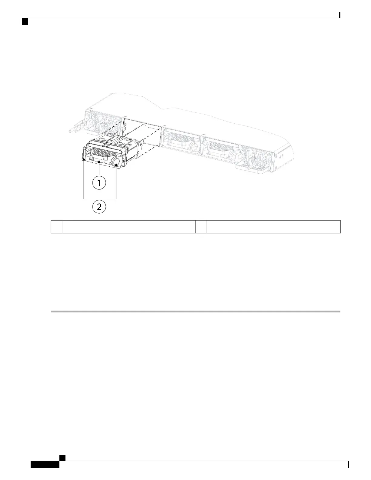
Step 3 Grasp the handle and pull the fan module out of the chassis.
Figure 44: Remove the Dual Fan Module
Squeeze tabsHandle1
Step 4 To replace a fan module, hold the fan module in front of the fan slot.
Step 5 Press the squeeze tabs on the sides of the fan module and push the it into the chassis.
Step 6 Grasp the handle and push until the fan module is properly seated.
If the system is powered on, listen for the fans. You should immediately hear the fans operating. If you do not hear the
fans, make sure the fan module is inserted completely into the chassis and the faceplate is flush with the outside surface
of the chassis.
Step 7 Verify that the fan is operational by checking the fan module LED. See Front Panel LEDs, on page 11 for a description
of the fan LEDs.
Remove and Replace the Power Supply Module
Power supply modules are hot-swappable. You can remove and replace power supply modules while the
system is running.
Safety Warnings
Take note of the following warnings:
Cisco Secure Firewall 4200 Series Hardware Installation Guide
68
Installation, Maintenance, and Upgrade
Remove and Replace the Power Supply Module