6-57
Hardware Installation Guide for Cisco 4000 Series Integrated Services Routers
OL-32185-02
Chapter 6 Install and Upgrade Internal Modules and FRUs
PoE Converter Power Supply Unit
Step 3 Replace PoE converter power supply filler. See “Remove PoE Power Supply Slot Filler” section for
details.
After you remove the PoE converter PSU, you need to either install a replacement power or put the filler.
Install the PoE Power Supply Slot Filler
You cannot keep the slot empty, you need to install the filler. To install a PoE power supply slot filler:
Step 1 Remove the bezel and fan tray from the router.
Step 2 Insert the filler tab into the slot on the chassis.
Step 3 Tighten the screws into the securing nuts on the chassis. See Figure 6-41 for details.
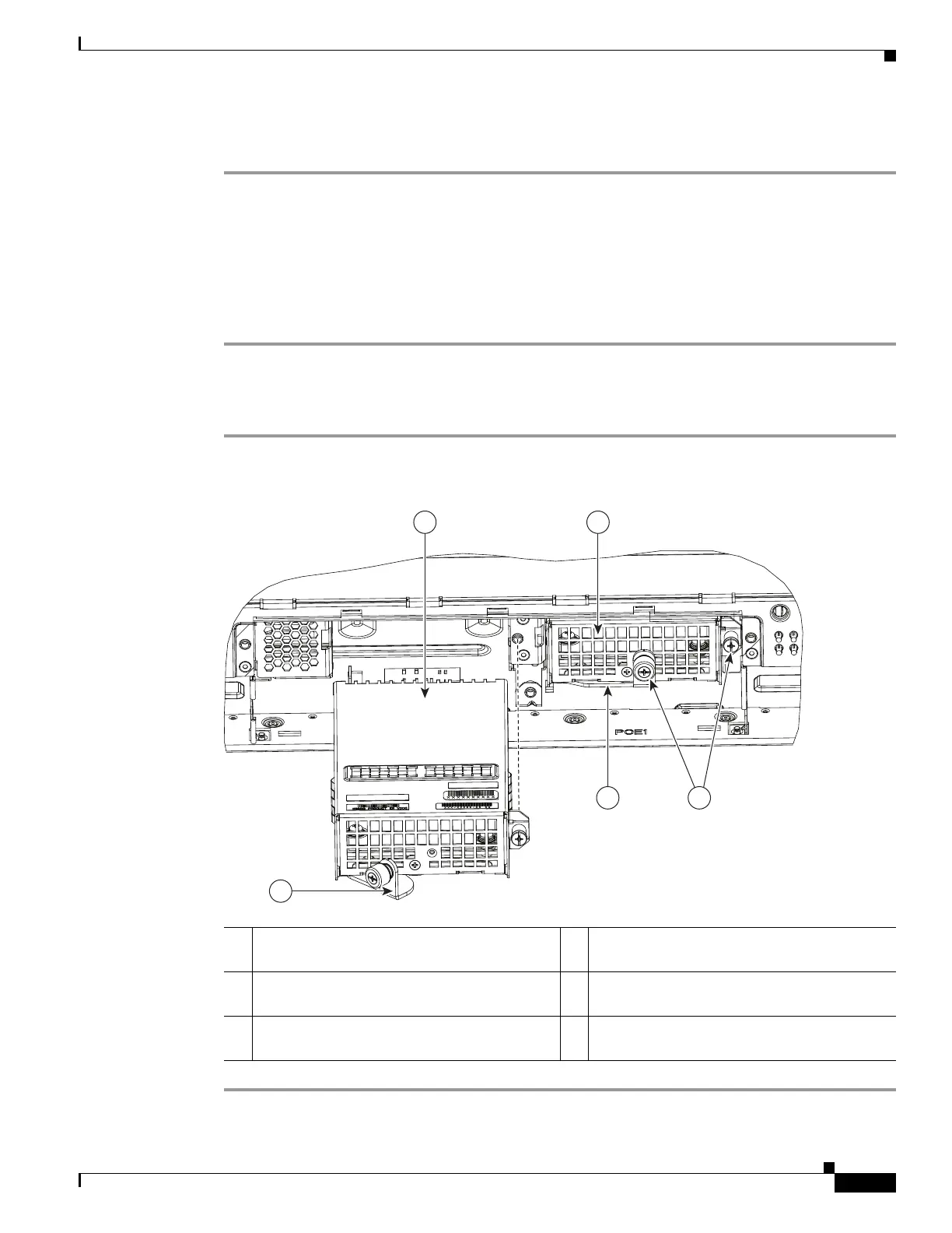
Figure 6-42 Install the PoE Converter Power Supply
1 Latch to secure module (shown open). 2 PoE converter module being installed in PoE
slot 0.
3 PoE converter module installed in PoE slot 1. 4 Screws to secure PoE module to router
chassis.
5 Latch to secure PoE converter module (shown
closed).
2 3
5 4
1
391818