2-3
Cisco Network Convergence System 6000 Series Routers Site Planning Guide
OL-29236-02
Chapter 2 Power and Cooling
Bonding and Grounding Guidelines
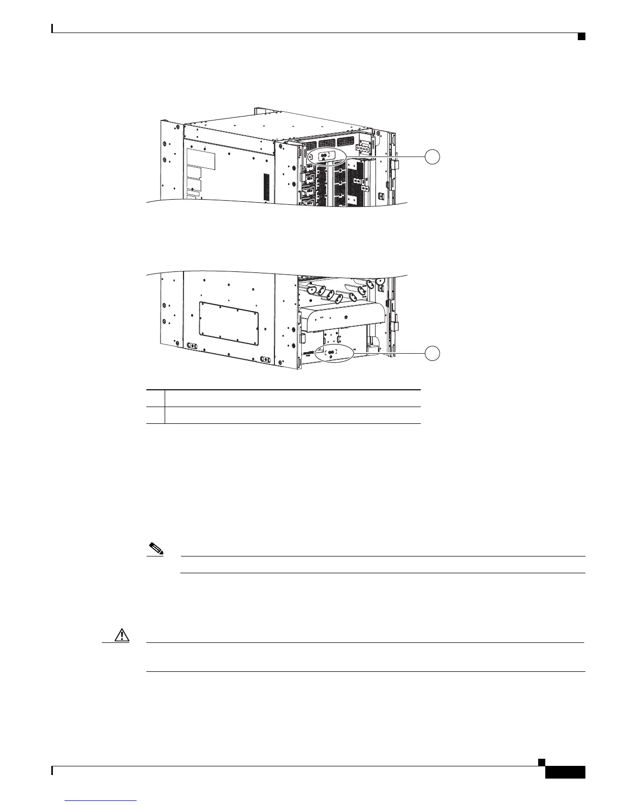
Figure 2-1 NEBS Bonding and Grounding Points—Rear Side of Chassis
To connect the chassis to a NEBS-compliant bonding and grounding system at your site, you must have
the following:
• One 180-degree angle (straight) grounding lug that has two M6 bolt holes with 0.63 inch spacing
center to center between them, and a wire receptacle able to accept a 6-AWG copper wire
(Figure 2-2).
• Four M6 bolts with integrated square cone locking washers (shipped pre-installed on the chassis,
two at each grounding point).
Note The chassis ground wire connectors have a torque value of 30 in-lb (3.39 N-m).
• Cisco recommends 2-6-AWG multistrand copper ground cable. This cable is not available from
Cisco; it is available from any commercial cable vendor. The cable should be sized according to
local and national installation requirements.
Caution The DC Return of the Cisco NCS 6008 chassis should remain isolated from the system frame and chassis
(DC-I: Isolated DC Return).
1 NEBS bonding and grounding point (upper)
2 NEBS bonding and grounding point (lower)
303676
1
2
 Loading...