4-3
Cisco Network Convergence System 6000 Series Routers Site Planning Guide
OL-29236-02
Chapter 4 Site Planning Considerations
Aisle Spacing and Maintenance Access Floor Plan
Aisle Spacing and Maintenance Access Floor Plan
The floor plan for the Cisco NCS 6008 chassis must include enough space to install the chassis and allow
sufficient airflow for the system. The floor plan must also provide enough room to access chassis
components for maintenance (for example, to remove fan trays, power components, cables, and air
filters).
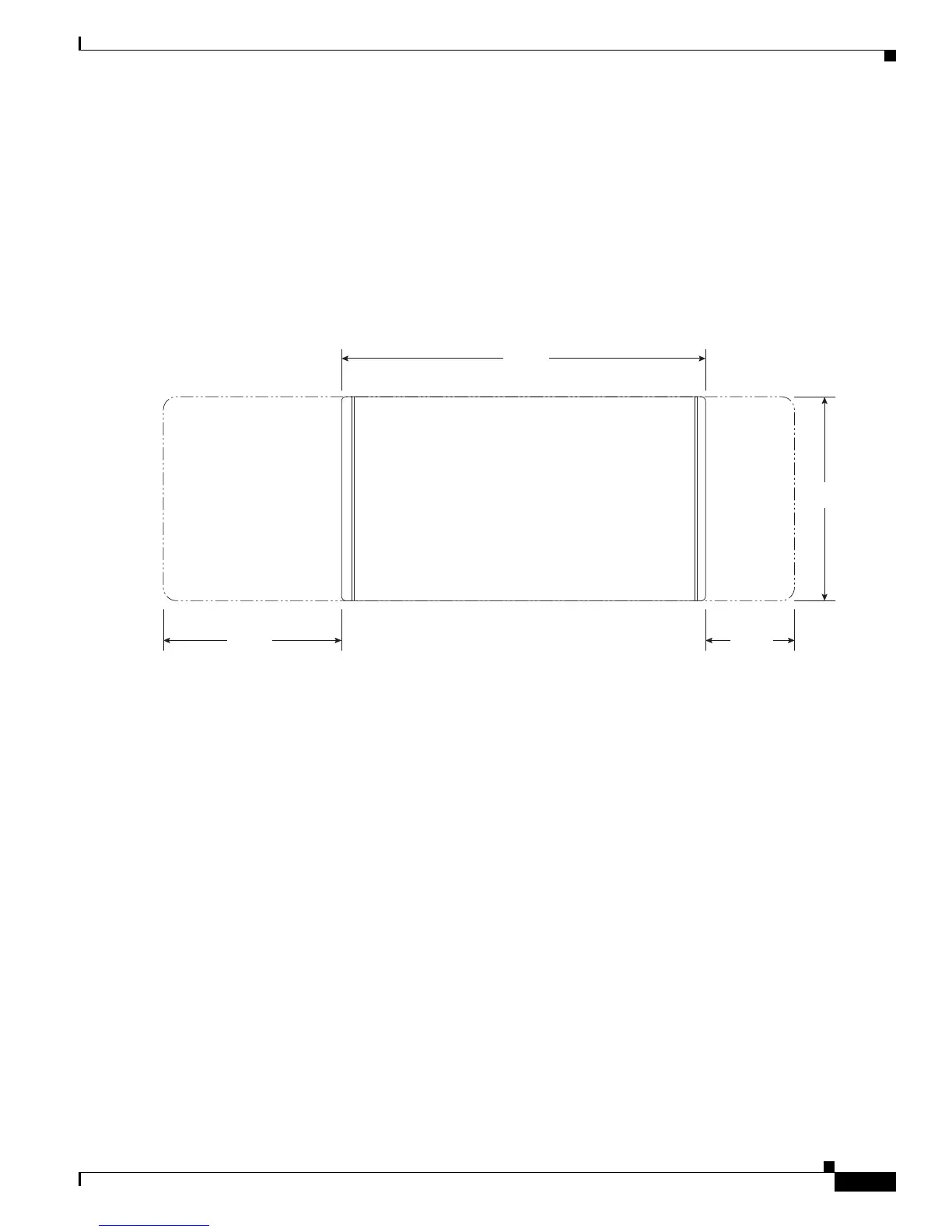
Figure 4-1 shows a top-down view of the chassis footprint required for installation.
Figure 4-1 Chassis Footprint for Installation and Maintenance
Drill Hole Template
Before moving the chassis into place and securing it, you must make sure that your site is prepared.
Because of its size and weight, the chassis must be securely bolted to the floor. Several possible bolting
configurations exist for the chassis. Cisco provides a drill hole template to identify the chassis footprint
and the pattern of holes that must be drilled into the floor for the mounting hardware that secures the
chassis to the floor.
Power and Cooling Requirements
See Chapter 2, “Power and Cooling,” for information about the power and cooling systems on the chassis
and for information about the power and cooling requirements at the installation site.
31.70
42.00
Front aisle space required for removal of
fan trays/line cards/filter
14.00
Rear aisle space required for
removal of FC/RP cards
23.60
All measurements in inches
Front Rear
 Loading...