2-4
Cisco Network Convergence System 6000 Series Routers Site Planning Guide
OL-29236-02
Chapter 2 Power and Cooling
DC Power Systems
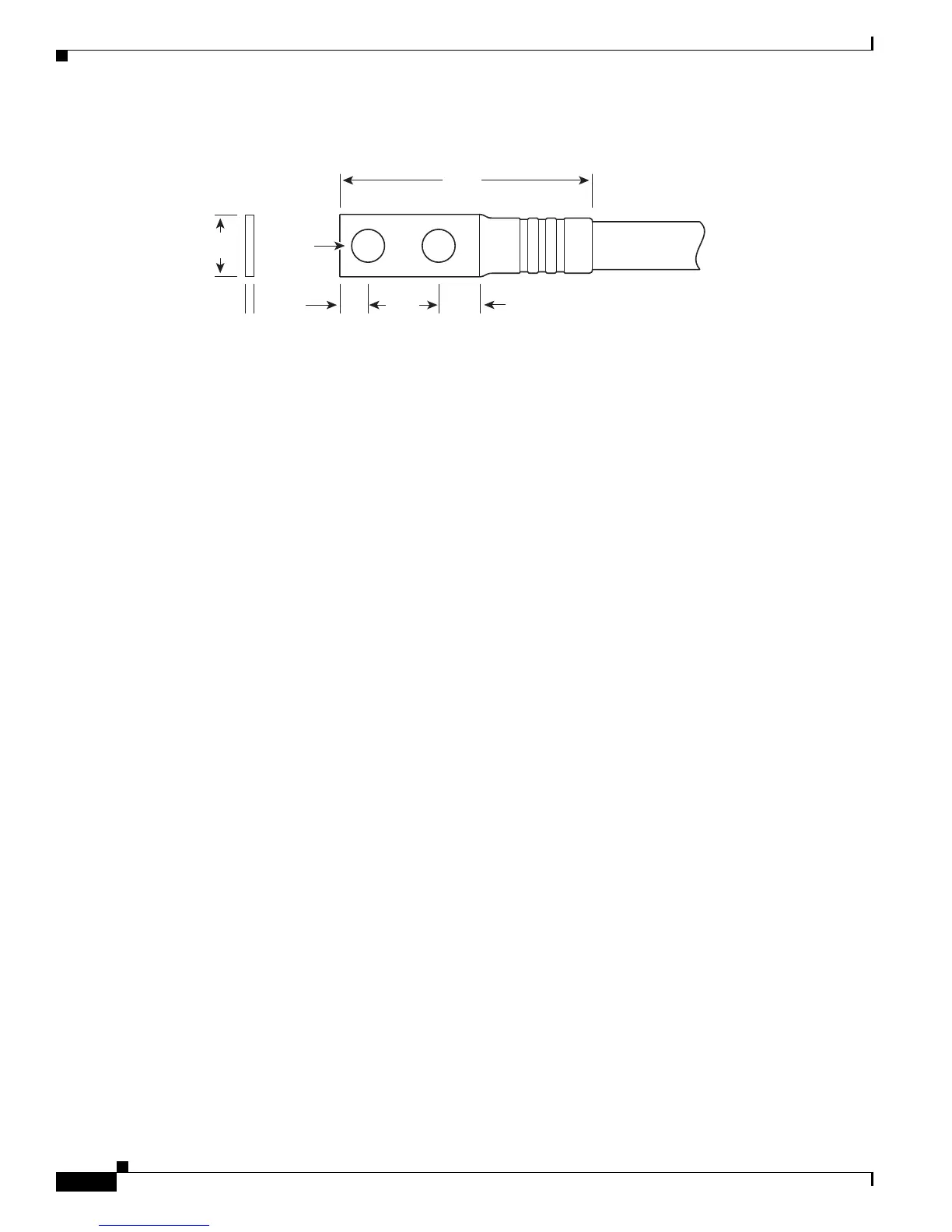
Figure 2-2 180-Degree Angle Straight Barrel Grounding Lug
DC Power Systems
The DC input power system provides the necessary power for all chassis components. Site power
requirements differ, depending on the source voltage used.
DC Power Requirements
Each DC-powered chassis contains six DC power trays. The upper three DC power trays are contained
within power shelf 0, and the lower three DC power trays are contained within power shelf 1. Each power
shelf has a Power bus Control Module (PCM) with its own 1/0 power switch. Each DC power tray can
contain up to four DC PMs. The DC power trays and PMs are field replaceable.
In addition to the requirements described in the “General Power and Grounding Requirements” section
on page 2-1, DC input power requirements are as follows:
• Each DC power tray requires up to four DC input feeds of either –48 VDC (nominal), 50 A or
–60 VDC (nominal), 40 A. The power tray accepts input DC power in the range –40 to –72 VDC.
• To operate the system with N+N DC power redundancy requires access to the "A" and "B" power
busses at the Central Office (CO). This dual connectivity provides N+N power redundancy in case
a power source fails.
–
CO “A” power connected to power trays 0, 1, and 2, with up to four –48/–60 VDC inputs per
power tray.
–
CO “B” power connected to power trays 3, 4, and 5, with up to four –48/–60 VDC inputs per
power tray.
• Required input current is as follows:
–
50 A at –48 VDC nominal input voltage.
–
40 A at –60 VDC nominal input voltage
–
60 A at minimum input voltage (–40 VDC).
• An “allpole” separation of the power source is not required. The DC PM is an isolated DC/DC
converter with no galvanic connection between “L+” and the chassis. In addition, the “L+”
potentials of each PM are isolated from each other.
Crimp area
310354
2.40
+/- .06
0.60
+/- .04
0.10
+/- .01
0.25
+/- .04
0.380.63
+/- .02
End View
Ø 0.27
+/- .02
2 holes
All measurements in inches
 Loading...