2-7
Cisco Network Convergence System 6000 Series Routers Site Planning Guide
OL-29236-02
Chapter 2 Power and Cooling
AC Power Systems
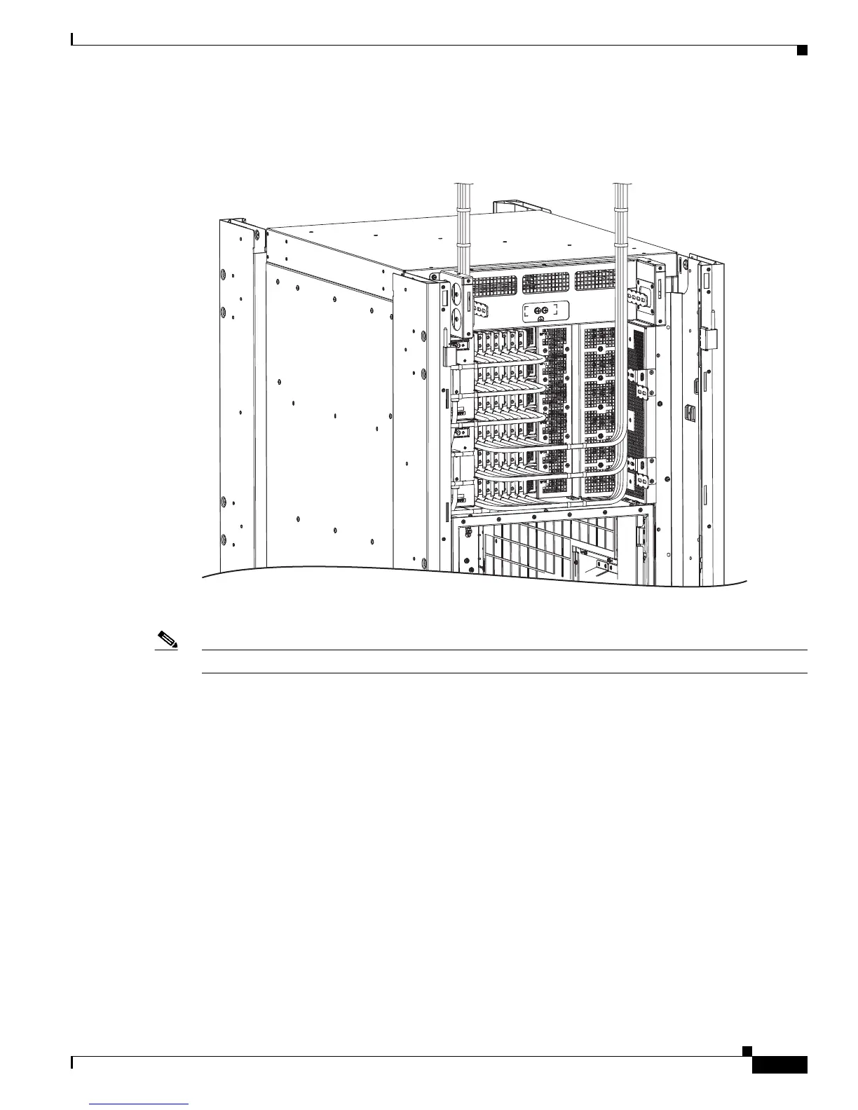
Figure 2-4 shows the DC input power cables connected to the DC power tray terminal block.
Figure 2-4 DC Power Tray Power Cable Connections
Note In the DC power system, the power wire connectors have a torque value of 45 to 55 in-lb (5.1 to 6.2 N-m).
AC Power Systems
The AC input power system provides the necessary power for all chassis components. Site power
requirements differ, depending on the source voltage used.
AC Power Requirements
Each AC-powered chassis contains six AC power trays. The upper three AC power trays are contained
within power shelf 0, and the lower three AC power trays are contained within power shelf 1. Each power
shelf has a PCM with its own 1/0 power switch. Each AC power tray can contain up to three AC PMs.
The AC power trays and PMs are field replaceable.
In addition to the requirements in the “General Power and Grounding Requirements” section on
page 2-1, AC input power requirements are as follows:
• Two separate and independent AC power sources are required to provide N+N power redundancy in
case a power source fails.
303754
 Loading...